



Không ai có thể chọn được máy bơm phù hợp cho đến khi yêu cầu công việc được xác định cụ thể bằng các con số. “Bơm một lượng dung môi vào bể chứa ngày” không phải là thông số kỹ thuật — đường cong hiệu suất của máy bơm mới là thông số kỹ thuật. Trước khi có thể lựa chọn máy bơm ly tâm hoặc máy bơm xoáy, cần phải xác định ba thông số: lưu lượng mà quy trình cần, cột áp mà máy bơm phải tạo ra để cung cấp lưu lượng đó, và áp suất hút có sẵn để máy bơm không bị xâm thực. Nếu xác định chính xác ba thông số này, việc lựa chọn sẽ trở nên đơn giản. Nếu tính sai cột áp hoặc bỏ qua việc kiểm tra áp suất hút, bạn sẽ phải đối mặt với tình trạng máy bơm quá nóng, bị xâm thực hoặc không bao giờ đạt được lưu lượng yêu cầu.
Bài viết này sẽ hướng dẫn chi tiết quy trình tính toán mà chúng tôi thực hiện khi nhận được yêu cầu từ khách hàng — bắt đầu từ lưu lượng, tiếp theo là tổng cột áp động, sau đó là NPSH, và cuối cùng là công suất cần thiết để vận hành động cơ — kèm theo các công thức, một ví dụ minh họa đầy đủ có thể sao chép, cùng những sai sót trong việc tính toán kích thước gây ra phần lớn các vấn đề. Phương pháp này áp dụng cho các loại bơm động lực quay (bơm ly tâm và bơm xoáy); các loại bơm thể tích được tính toán theo cơ sở khác, được nêu rõ ở phần cuối.
Ba con số xác định điểm thuế
Điểm làm việc của máy bơm là điểm mà máy bơm phải hoạt động, và cần ba thông số đầu vào để xác định chính xác điểm này:
● Lưu lượng (Q) — lưu lượng mà quá trình cần cho mỗi đơn vị thời gian, tính bằng m³/h hoặc L/phút (hoặc GPM).
● Tổng cột áp động (TDH, hay H) — tổng năng lượng mà máy bơm phải cung cấp để di chuyển lưu lượng đó, được biểu thị bằng chiều cao cột chất lỏng, tính bằng mét (hoặc feet).
● Độ cao hút dương khả dụng (NPSHa) — Áp suất tuyệt đối tại cửa vào của máy bơm cao hơn áp suất hơi của chất lỏng bao nhiêu, yếu tố này quyết định liệu máy bơm có bị hiện tượng cavitation hay không.
Lưu lượng và cột áp cùng xác định điểm trên đường cong đặc tính của máy bơm. Giá trị NPSHa được so sánh với giá trị NPSH yêu cầu của máy bơm để đảm bảo máy bơm đã chọn thực sự có thể hoạt động ở điều kiện đó mà không bị hiện tượng xâm thực. Công suất được tính toán dựa trên lưu lượng và cột áp, và từ đó xác định loại động cơ. Hãy thực hiện các bước theo thứ tự này.
Lưu lượng: Bắt đầu từ quy trình
Lưu lượng thường được xác định bởi quy trình, chứ không phải bởi máy bơm. Một vòng tuần hoàn của bộ trao đổi nhiệt cần một tốc độ tuần hoàn nhất định để truyền nhiệt; một dây chuyền chiết rót cần đổ đầy bình chứa trong một khoảng thời gian nhất định; một nhiệm vụ chuyển tải cần làm rỗng một xe bồn trong một ca làm việc. Tính toán tốc độ mà quy trình thực sự yêu cầu và sử dụng nhu cầu đỉnh, không phải giá trị trung bình, nếu hai giá trị này khác nhau. Một lưu ý: không nên tăng lưu lượng “để đề phòng”. Một giá trị lưu lượng quá lớn sẽ làm tăng cột áp, công suất và kích thước máy bơm, đồng thời khiến máy bơm hoạt động ở phần không phù hợp trên đường cong hiệu suất của nó. Hãy chọn kích thước phù hợp với yêu cầu thực tế và sử dụng bộ điều khiển tốc độ biến thiên nếu nhu cầu thay đổi.
Tổng cột áp động: Con số mà nhiều người thường hiểu nhầm
Tổng cột áp động là nguyên nhân phổ biến nhất dẫn đến việc tính toán công suất máy bơm không chính xác, bởi vì người ta chỉ dựa vào cột áp tĩnh mà bỏ qua các yếu tố còn lại. Để có cái nhìn toàn diện, cần tính đến bốn yếu tố sau:
TDH = cột tĩnh + cột ma sát + cột áp suất + cột vận tốc
● Áp suất tĩnh — chênh lệch độ cao theo phương thẳng đứng giữa mặt chất lỏng hút và mặt chất lỏng xả. Đây là phần mà hầu hết mọi người đều nhớ.
● Độ cao ma sát — lượng năng lượng bị mất do ma sát trong hệ thống ống dẫn hút và xả, van và các phụ kiện. Lượng tổn thất này tỷ lệ thuận với bình phương của lưu lượng, do đó nó tăng nhanh trong các đường ống dài hoặc có đường kính không đủ, và bạn có thể tra cứu giá trị này trên bảng tổn thất do ma sát hoặc tính toán bằng phương pháp Darcy-Weisbach hoặc Hazen-Williams dựa trên kích thước ống, chiều dài và các phụ kiện.
● Áp suất cột nước — only if the suction or discharge vessel is pressurized or under vacuum. Convert the pressure difference to a height of liquid: head in metres = pressure (kPa) ÷ (ρ × 9.81). For open tanks at both ends, this term is zero.
● Đầu tốc độ — the kinetic energy of the moving fluid, V²÷2g. At normal pipe velocities it is small, and for most sizing it is left out.
Add the parts and you have the head the pump must generate at the required flow. The single biggest sizing error is using static head only: a pump sized on the 16 m lift in the example below, ignoring the 5 m of friction, would fall about 5 m short of head and never reach its design flow.
Một ví dụ minh họa, từ đầu đến cuối
Take a real-shaped duty: transfer 20 m³/h of an organic solvent, specific gravity 0.87, vapour pressure about 12 kPa at 30°C, at a site near sea level (atmospheric pressure 101 kPa). The suction tank surface sits 2 m above the pump (flooded suction); the discharge tank surface is 18 m above the pump; both tanks are open to atmosphere. Suction-line friction is 0.6 m and discharge-line friction is 4.5 m at this flow. Here is the whole calculation:
| Số lượng | Giá trị | Làm thế nào |
| Lưu lượng yêu cầu (Q) | 20 m³/h | Nhu cầu về quy trình |
| Áp suất tĩnh | 16 m | Discharge surface 18 m − suction surface 2 m |
| Friction head (suction + discharge) | 5,1 mét | 0.6 + 4.5, from friction charts |
| Độ cao cột áp | 0 m | Both tanks atmospheric |
| Total dynamic head (TDH) | 21.1 m | 16 + 5.1 |
| Atmospheric head (Ha) | 11.8 m | 101 kPa ÷ (870 × 9.81) |
| Suction static (Hz) | +2 m | Flooded suction, surface above pump |
| Suction friction (Hf) | 0.6 m | Suction line only |
| Vapour-pressure head (Hvp) | 1.4 m | 12 kPa ÷ (870 × 9.81) |
| NPSH available | 11.8 m | 11.8 + 2 − 0.6 − 1.4 |
| NPSH required (from curve) | 3.0 m | Manufacturer, at 20 m³/h |
| NPSH margin | 8.8 m | 11.8 − 3.0 → safe |
| Hydraulic power | 1.0 kW | 20 × 21.1 × 0.87 ÷ 367 |
| Shaft power (55% eff.) | 1.8 kW | 1.0 ÷ 0.55 |
| Motor (next size up) | 2.2 kW | Shaft power plus margin |
The duty point is 20 m³/h at 21.1 m, the suction is safe with nearly 9 m of NPSH margin, and the motor is 2.2 kW. The sections below explain the suction and power lines in more detail.
NPSH: Will the Pump Cavitate?
Cavitation is what happens when the pressure at the pump inlet drops below the fluid's vapour pressure: vapour bubbles form and then collapse violently inside the pump, eroding the impeller and bearings and shaking the whole machine. The suction check exists to prevent it. NPSH available is what the system offers at the inlet, calculated in absolute terms:
NPSHa = Ha + Hz − Hf − Hvp
Ha is the absolute pressure on the liquid surface as a head (atmospheric pressure at the site altitude); Hz is the static suction head, positive for a flooded suction and negative for a suction lift; Hf is the suction-line friction; and Hvp is the fluid's vapour pressure as a head. Two points catch people out. NPSH is always worked in absolute pressure, because vapour pressure is an absolute property, and the velocity head is not included. NPSH required (NPSHr) is the other half — it is a property of the pump, read off the manufacturer's curve at the operating flow, and it rises with flow, so always check it at the maximum flow, not the average.
The rule is NPSHa must exceed NPSHr with a margin. The Hydraulic Institute recommends NPSHa of at least 1.5 times NPSHr, or NPSHr plus roughly 0.6 to 1 m, whichever is greater. Hot fluids near their boiling point and high-altitude sites both eat into NPSHa fast, and suction lift makes it worse — practical suction lift rarely exceeds 4 to 5 m even though atmospheric pressure could in theory support about 10 m of cold water. If the margin is thin, raise the source level, shorten and widen the suction line, or cool the fluid. We go deeper into the suction side and the fixes on our preventing pump cavitation page.
Power and Motor Size
Power follows from flow and head. The hydraulic power — the useful work delivered to the fluid — is:
Hydraulic power (kW) = Q × H × SG ÷ 367, with Q in m³/h and H in metres.
That is the theoretical figure. The shaft (or absorbed) power the motor actually has to deliver is higher, because no pump is 100% efficient: shaft power = hydraulic power ÷ pump efficiency. In the example, 1.0 kW hydraulic at a 55% pump efficiency is about 1.8 kW at the shaft, so the next motor size up — 2.2 kW — gives a sensible margin. Two rules keep this honest. Size the motor for the worst case on the curve, because absorbed power rises with flow, so check it at the maximum flow the pump might see, not just the duty point. And do not over-pad: an oversized motor wastes energy every hour it runs and is a classic false economy. Pump efficiency itself is highest near the best efficiency point (BEP), which is the next thing to get right — see our industrial centrifugal pump efficiency guide.
Common Sizing Mistakes
Most sizing problems come from the same handful of shortcuts:
● Using static head only. Forgetting friction head is the classic error and leaves the pump short of its design flow.
● Padding the flow or head “to be safe.” Arbitrary safety factors push the pump off its best efficiency point, waste energy, and accelerate wear. Oversizing is the least safe choice, not the most.
● Skipping the NPSH check. A pump that looks right on flow and head will still cavitate if the suction was never verified.
● Checking NPSH and power at the duty point only. Both NPSHr and absorbed power rise with flow, so check them at the maximum flow.
● Undersizing the suction line. A thin suction line adds friction exactly where NPSH is tight.
● Operating far from BEP. Aim for a pump that runs at roughly 80–110% of its best efficiency point at the duty flow.
● Ignoring specific gravity and viscosity. A denser fluid needs more power for the same head, and a viscous fluid changes both friction and pump performance.
From Duty Point to Pump
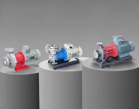
With flow, head, and NPSHa in hand, you can select the pump. The duty shape points to the type: high flow at moderate head suits a centrifugal pump; high head at low flow suits a vortex (regenerative-turbine) pump, covered in our industrial vortex pump selection guide; zero-leakage or corrosive duties point to a sealless build, covered in our magnetic drive pump selection guide. The figures above are for rotodynamic pumps. A positive-displacement pump — a gear or vane pump for viscous or precisely metered duties — is sized differently: its flow is set by displacement and speed rather than by a head-flow curve, and the system pressure is whatever the pump has to push against. Our Positive Displacement Pump Series and the Chemical Pump Series cover those options, and the full industrial pump range spans the range.
Send Us the Duty Point and We Will Size It
If you would rather have the calculation checked than done from scratch, send us the flow, the suction and discharge layout (elevations, pipe sizes and lengths, fittings), the fluid with its specific gravity, vapour pressure, and temperature, and any vessel pressures. Our engineering team will return the total dynamic head, the NPSH check, the power, and a matched pump — sealless magnetic-drive, vortex, centrifugal, or positive-displacement — for the duty.
Talk to our team: Contact Aulank | WhatsApp: +86 13773157367 | Email: info@aulankpump.com
Related reading: industrial vortex pump selection guide · magnetic drive pump selection guide