


Ấn Độ sản xuất khoảng 20% tổng sản lượng thuốc generic trên thế giới và sở hữu nhiều cơ sở sản xuất được chứng nhận WHO-GMP hơn bất kỳ quốc gia nào khác. Đằng sau quy mô đó là sự phát triển sản xuất vẫn đang tăng tốc vào năm 2026: Chương trình PLI trung ương dành cho Thuốc nguyên liệu (kinh phí 69,4 tỷ rupee) đã phê duyệt 48 dự án bao gồm 33 KSM/DIs/API quan trọng với 481,4 tỷ rupee vốn đầu tư đã được triển khai, và Chương trình PLI rộng hơn dành cho Dược phẩm (kinh phí 1.500 tỷ rupee) đã thu hút 4.192 tỷ rupee vốn đầu tư thực tế từ 55 công ty được lựa chọn. Các đợt nộp đơn xin API/KSM mới vẫn tiếp tục mở đến năm 2026, và các khu công nghiệp dược phẩm thô ở Gujarat, Andhra Pradesh và Himachal Pradesh đang bắt đầu đưa các nhà máy chế biến vào hoạt động. Mỗi nhà máy trong số đó đều phụ thuộc vào một số ít trạm xử lý chất lỏng để thực sự hoạt động — và các máy bơm tại các trạm đó không thể hoán đổi cho các đơn vị công nghiệp nói chung.
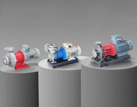
Trong hơn một thập kỷ qua, chúng tôi đã cung cấp các loại bơm truyền động từ tính và bơm động cơ kín cho các nhà sản xuất thiết bị dược phẩm OEM tại Ấn Độ cũng như các nhà máy sản xuất hoạt chất dược phẩm (API) của người dùng cuối. Các mẫu lỗi trong quá trình vận hành mà chúng tôi quan sát được là nhất quán: bơm được thiết kế cho nước quá trình sạch bị hỏng khi xử lý dòng HCl loãng, bơm có phớt cơ khí rò rỉ dung môi vào các khu vực được phân loại theo tiêu chuẩn PESO, và bơm định lượng có dải điều chỉnh quá rộng gây ra thể tích mẻ không đồng đều, dẫn đến vi phạm yêu cầu về độ đồng nhất hàm lượng theo tiêu chuẩn USP<905>. Hướng dẫn này trình bày cách lựa chọn bơm cho tám trạm xử lý chất lỏng chính trong nhà máy dược phẩm tại Ấn Độ — từ tuần hoàn trong bể phản ứng tổng hợp API đến định lượng trong công đoạn bào chế — với sự chú trọng vào các yêu cầu cGMP, ICH Q7 và PESO áp dụng trong thực tiễn quản lý của Ấn Độ.
1. Các trạm bơm của một nhà máy dược phẩm hiện đại ở Ấn Độ
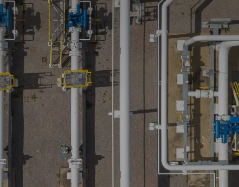
Một nhà máy sản xuất API hoặc dược phẩm thường có từ tám đến mười hai nhiệm vụ bơm riêng biệt, mỗi nhiệm vụ có thành phần hóa học của chất lỏng, nhiệt độ và áp suất khác nhau, cũng như các tình huống hỏng hóc nghiêm trọng nhất hoàn toàn khác nhau. Việc nắm rõ toàn bộ bối cảnh là điều kiện tiên quyết để đưa ra các thông số kỹ thuật hợp lý cho từng trạm bơm:
● Hệ thống tuần hoàn trong bình phản ứng API — tuần hoàn qua lớp vỏ và cụm ống của bình phản ứng được lót thủy tinh hoặc làm bằng Hastelloy. Quá trình tổng hợp hóa học có tính ăn mòn cao, áp suất làm việc 5–6 bar, thay đổi mẻ thường xuyên.
● Vận chuyển dung môi — vận chuyển số lượng lớn methanol, isopropanol, acetone, ethanol, MEK, DMF, NMP và các dung môi clo hóa từ khu bồn chứa đến lò phản ứng. Các khu vực được phân loại theo tiêu chuẩn PESO với yêu cầu về động cơ chống cháy nổ.
● Chuyển axit và bazơ — HCl, H₂SO₄, NaOH, KOH đậm đặc được bơm vào các bình phản ứng để điều chỉnh độ pH, tạo muối và kết tinh.
● Hệ thống gia nhiệt và làm mát vỏ lò phản ứng — các vòng tuần hoàn dầu nhiệt cho quá trình chưng cất hồi lưu nhiệt độ cao, dung dịch muối làm lạnh hoặc glycol cho quá trình kết tinh và làm mát đột ngột.
● Phân phối nước tinh khiết và nước dùng để tiêm (WFI) — Nước tinh khiết đạt tiêu chuẩn USP<1231> và nước dùng để tiêm (WFI) được tuần hoàn qua các vòng ống chính ở nhiệt độ 70–85 °C.
● Vệ sinh và tiệt trùng theo quy trình CIP/SIP — dung dịch kiềm nóng, dung dịch axit nóng và nước ngưng tụ từ hơi nước được tuần hoàn qua hệ thống thiết bị giữa các mẻ sản xuất.
● Công thức và định lượng vô trùng — quá trình chuyển dịch chính xác các dung dịch hoạt chất (API), tá dược và dung môi vào các bồn trộn và dây chuyền chiết rót.
● Tái chế nước thải và dung môi — việc tái chế dung môi từ các thiết bị ngưng tụ, dòng hồi lưu của cột chưng cất, và việc chuyển nước thải sang các nhà máy xử lý ZLD đang ngày càng được yêu cầu bắt buộc tại các cụm công nghiệp dược phẩm ở Ấn Độ.
Có năm yêu cầu bắt buộc áp dụng cho tất cả các trạm này: không rò rỉ dung môi được kiểm soát và các chất trung gian độc hại, không có sự nhiễm bẩn ion kim loại hoặc chất đàn hồi trong chất lỏng quá trình, khả năng truy xuất nguồn gốc vật liệu được ghi chép đầy đủ cho các cuộc kiểm toán cGMP, khả năng chịu được chu kỳ nhiệt CIP/SIP thường xuyên mà không bị suy giảm, và tuân thủ các tiêu chuẩn điện theo chứng nhận của Tổ chức An toàn Dầu mỏ và Chất nổ Ấn Độ (PESO) đối với các khu vực xử lý dung môi.
2. Hệ thống tuần hoàn trong lò tổng hợp API: Lựa chọn bơm có lớp lót thủy tinh và bơm Hastelloy
Quá trình tổng hợp API là công đoạn đòi hỏi điều kiện hóa học khắc nghiệt nhất trong nhà máy. Các phản ứng liên quan đến các axit khoáng đậm đặc (HCl, HBr, H₂SO₄), bazơ mạnh, các chất trung gian halogen hóa, chất oxy hóa và các phản ứng được xúc tác bởi kim loại. Bình phản ứng thường được làm bằng thép carbon tráng men thủy tinh để chịu được tính ăn mòn cao, hoặc Hastelloy C-22/C-276 trong trường hợp hóa học cho phép sử dụng kết cấu kim loại. Các máy bơm tái tuần hoàn nội dung bình phản ứng — qua các bộ trao đổi nhiệt bên ngoài, hệ thống lọc và các vòng lấy mẫu — cần phải tương thích với vật liệu đó.
Ba quyết định thực tiễn trong việc lựa chọn bơm cho các ứng dụng trong lò phản ứng API:
● Các bộ phận tiếp xúc với chất lỏng được lót bằng polyme flo cho các ứng dụng hóa học liên quan đến halogen và axit. Vỏ bơm được lót bằng PTFE, ETFE hoặc PFA mang lại tính trơ hóa học tương đương với chính bình phản ứng lót thủy tinh. Các bộ phận bằng thép không gỉ phía bơm sẽ làm rò rỉ sắt vào mẻ sản phẩm và không đáp ứng được giới hạn tạp chất nguyên tố theo tiêu chuẩn USP<232> chỉ sau vài tháng. Bơm truyền động từ tính lót PTFE AMC-F của chúng tôi là sản phẩm được xuất xưởng thường xuyên nhất đến các nhà máy API tại khu vực Hyderabad và Vapi để phục vụ cho các ứng dụng liên quan đến HCl, HBr và các chất trung gian halogen hóa.
● Kiến trúc truyền động từ tính không có phớt. Các phớt cơ khí thường hỏng theo quy luật nhất định trong dịch vụ tổng hợp API — sự ăn mòn của dung môi đối với vật liệu đàn hồi, quá trình kết tinh của muối hòa tan tại bề mặt phớt, cùng với chu kỳ nhiệt do thay đổi mẻ sản xuất thường xuyên, kết hợp lại khiến tuổi thọ phớt thường chỉ từ 6–12 tháng. Máy bơm truyền động từ tính sử dụng ổ trục cacbua silic loại bỏ hoàn toàn phớt động. Để có cái nhìn tổng quan hơn về kỹ thuật, hãy tham khảo hướng dẫn lựa chọn bơm truyền động từ công nghiệp của chúng tôi.
● Khả năng chịu được khí lẫn trong chất lỏng và hoạt động trong điều kiện khô một phần. Bơm tuần hoàn trong lò phản ứng phải đối mặt với các túi khí do sự giải phóng CO₂, sự thoát hydro trong các phản ứng khử, và hiện tượng cuốn khí trong quá trình nạp nguyên liệu vào lò phản ứng. Bơm ly tâm bị xâm thực do những yếu tố này; trong khi đó, bơm từ tính xoáy tuabin tái tạo có thể chịu được 10–15% khí lẫn vào mà không bị mất áp suất. Đây chính là lợi thế xử lý khí quan trọng trong bơm MTC và quá trình chuyển bùn.
Đối với các dịch vụ API có mức độ tác động thấp (quá trình tinh chế trung gian, dung dịch muối hữu cơ, các quy trình ở pH trung tính), một máy bơm xoáy từ tính bằng thép không gỉ 316L thường là đủ. Dòng máy bơm xoáy từ tính bằng thép không gỉ MDH đáp ứng yêu cầu này cho các nhà tích hợp nhà máy API tại Gujarat và Maharashtra mà chúng tôi hợp tác trực tiếp.
3. Bơm chuyển dung môi: Methanol, IPA, Acetone, DMF, NMP và các dung môi clo hóa
Một nhà máy sản xuất dược phẩm nguyên liệu (API) quy mô lớn thông thường sử dụng từ 5 đến 15 loại dung môi hữu cơ khác nhau trong quá trình sản xuất. Các trạm bơm vận chuyển các dung môi này giữa khu bể chứa, bể chứa tạm thời và cổng nạp của bình phản ứng chính là nơi mà hầu hết các nhà máy tích tụ những rủi ro tiềm ẩn. Có hai vấn đề nổi bật:
● Tuân thủ quy định về khu vực được phân loại theo tiêu chuẩn PESO. Các khu vực xử lý dung môi tại các nhà máy ở Ấn Độ được PESO phân loại thành Khu vực 1 hoặc Khu vực 2 dựa trên khả năng xuất hiện môi trường dễ cháy. Động cơ bơm trong các khu vực này phải có chứng nhận PESO hợp lệ (tương đương với chứng nhận ATEX tại Ấn Độ). Động cơ cảm ứng tiêu chuẩn không được chấp nhận; máy bơm phải được đặt hàng với các biến thể động cơ chống cháy nổ phù hợp với nhóm khí và loại nhiệt độ của dung môi cụ thể. Methanol, ethanol, acetone và IPA thuộc Nhóm khí IIA T2 trong hầu hết các nhà máy; DMF và NMP thuộc IIA T3 do nhiệt độ tự cháy cao hơn.
● Khả năng tương thích của dung môi với các bộ phận tiếp xúc với chất lỏng và các bộ phận làm kín. NMP và DMF có khả năng ăn mòn các loại cao su Buna và EPDM tiêu chuẩn, đồng thời làm suy giảm hầu hết các loại FKM sau vài tháng sử dụng. Các dung môi clo hóa (dichloromethane, chloroform) còn làm suy giảm thêm thân bơm bằng thép carbon. Thông số kỹ thuật vật liệu phù hợp là các bộ phận tiếp xúc với chất lỏng phải được làm bằng thép không gỉ 316L tối thiểu, với cấu trúc lót PTFE hoặc PFA cho các ứng dụng liên quan đến dung môi clo hóa và halogen hóa. Cấu trúc truyền động từ tính loại bỏ hoàn toàn sự tiếp xúc của phớt động, loại bỏ nguyên nhân hỏng hóc cao su mà các bơm dung môi sử dụng phớt cơ học thường gặp phải.
Đối với việc bơm chuyển dung môi khối lượng lớn trong dải lưu lượng 50–300 L/phút – mức lưu lượng phổ biến tại các nhà máy sản xuất hoạt chất dược phẩm (API) ở Ấn Độ – mẫu bơm từ xoáy MDW bằng thép không gỉ 316L được đánh bóng gương, trang bị động cơ chống cháy nổ đạt chứng nhận PESO là cấu hình mà chúng tôi cung cấp thường xuyên nhất. Đối với các dòng dung môi chứa một lượng nhỏ HCl (ví dụ: methanol ướt từ quá trình thu hồi ngưng tụ), biến thể AMC-F lót PTFE là lựa chọn sạch hơn. Đối với dịch vụ thu hồi dung môi tinh khiết liên tục, nơi mà ngay cả việc tiếp xúc tĩnh với vòng đệm O-ring cũng không mong muốn, dòng bơm xoáy đóng hộp PWH/PWD/PWM là giải pháp thay thế về mặt cấu trúc — thiết kế động cơ đóng hộp loại bỏ hoàn toàn không gian khớp nối nam châm. Lý do sâu xa hơn về ba kiến trúc này có trong hướng dẫn công nghệ bơm động cơ đóng hộp của chúng tôi.
4. Hệ thống sưởi ấm và làm mát vỏ lò phản ứng: Mạch dầu nóng và mạch nước muối lạnh
Hầu hết các quy trình tổng hợp dược phẩm đều yêu cầu kiểm soát nhiệt độ vỏ lò một cách chính xác — từ 50–180 °C cho các phản ứng hồi lưu hữu cơ, từ −10 đến +5 °C cho quá trình làm lạnh kết tinh, và đôi khi lên đến 250 °C cho các bước khử nước ở nhiệt độ cao hoặc hình thành vòng. Vòng tuần hoàn chất lỏng nhiệt truyền nhiệt đến và đi từ vỏ bình phản ứng là một trong những trạm bơm chịu tải liên tục nhất trong nhà máy, và nó được chia thành hai nhiệm vụ riêng biệt:
Hệ thống tuần hoàn dầu nhiệt
Các chất lỏng truyền nhiệt gốc diphenyl hoặc aromatic alkylated (Therminol, Dowtherm, Marlotherm) lưu thông ở nhiệt độ 180–300 °C. Ở các nhiệt độ này, các chất đàn hồi trong bơm có phớt cơ khí tiêu chuẩn sẽ bị phân hủy trong vòng vài tháng, và bất kỳ sự rò rỉ dầu nóng nào từ phớt lên bề mặt mặt bích hoặc ống đều gây ra nguy cơ cháy nổ ngay lập tức. Để biết thêm thông tin về việc lựa chọn bơm dầu nóng, hãy tham khảo hướng dẫn lựa chọn bơm dầu nóng ly tâm so với bơm dầu nóng bánh răng của chúng tôi và trang giải pháp bơm nhiệt độ cao tổng quát hơn.
Đối với các ứng dụng vỏ bọc ở nhiệt độ 180–300 °C, cấu trúc bơm dầu nóng nhiệt độ cao kết hợp là tiêu chuẩn ngành tại các nhà máy ở Ấn Độ — trục ngắn làm mát bằng không khí giúp tách phớt cơ khí khỏi vùng quá trình nhiệt độ cao, cho phép phớt hoạt động ở nhiệt độ thấp hơn đáng kể. Bơm dầu nhiệt kết hợp WRY-H của chúng tôi có thể xử lý nhiệt độ lên đến 400 °C và là cấu hình mà chúng tôi đã chỉ định cho nhiều dự án nâng cấp nhà máy API ở Maharashtra và Telangana.
Hệ thống tuần hoàn dung dịch muối và glycol làm lạnh
Đối với quá trình kết tinh, làm nguội đột ngột và kiểm soát nhiệt độ sau phản ứng xuống đến −30 °C, dung dịch propylene glycol-nước hoặc ethylene glycol-nước với nồng độ 30–50% là chất lỏng truyền nhiệt thông dụng. Công việc của máy bơm nhẹ nhàng hơn về mặt hóa học so với dịch vụ lò phản ứng API nhưng có áp suất tương tự (4–6 bar) và chu kỳ làm việc liên tục. Máy bơm xoáy truyền động từ tính 316L tiêu chuẩn với động cơ PM đồng bộ điều khiển bằng VFD phù hợp hoàn hảo với công việc này. Dòng bơm xoáy từ tính bằng thép không gỉ MDS của chúng tôi đáp ứng dải lưu lượng tiêu biểu từ 100–500 L/phút.

5. Thông số kỹ thuật của bơm nước tinh khiết, WFI và bơm vòng lặp CIP/SIP
Nước tinh khiết (PW) theo tiêu chuẩn USP<1231> và Nước dùng để tiêm (WFI) theo tiêu chuẩn USP<1231> là những chất lỏng sạch nhất trong nhà máy dược phẩm. Đây cũng là những nhiệm vụ đòi hỏi khắt khe nhất đối với bơm từ góc độ kiểm soát ô nhiễm. Ba hạn chế kỹ thuật sau đây quyết định việc lựa chọn bơm cho ứng dụng này:
● Lớp hoàn thiện bề mặt vệ sinh. Các bề mặt tiếp xúc với chất lỏng phải được đánh bóng điện hóa đạt độ nhám bề mặt Ra 0,4 µm hoặc tốt hơn đối với hệ thống nước tinh khiết (PW), và Ra 0,25 µm đối với hệ thống đường ống chính nước tiệt trùng (WFI). Các bề mặt hoàn thiện tiêu chuẩn công nghiệp (Ra 0,8–1,6 µm) giữ lại protein và tạo ra các điểm kết tinh cho màng sinh học. Các kết nối tri-clamp vệ sinh (DIN 32676 hoặc ASME BPE) là bắt buộc.
● Xả cạn và tránh đoạn ống chết. Cấu trúc hình học của bơm phải đảm bảo có thể xả cạn hoàn toàn mà không để lại các vùng nước đọng. Các bơm xoắn ốc tiêu chuẩn có hướng xả đáy tạo ra các vùng chết, không đáp ứng tiêu chuẩn về màng sinh học của USP; do đó, cần phải sử dụng các cấu hình xả ngang tự thoát nước hoặc các thiết kế bơm truyền động từ tính dọc không có vùng nước đọng.
● Tương thích với CIP/SIP. Cùng một máy bơm được làm sạch tại chỗ bằng dung dịch NaOH hoặc HNO₃ nồng độ 1–2% ở nhiệt độ 75–85 °C, và tiệt trùng tại chỗ bằng hơi nước bão hòa ở nhiệt độ 121–134 °C. Các vật liệu tiếp xúc với chất lỏng phải chịu được chu trình nhiệt này mà không bị biến dạng hoặc làm suy giảm hiệu quả của phớt. Kiến trúc truyền động từ tính với vòng bi cacbua silic xử lý chu kỳ nhiệt một cách đáng tin cậy; các thiết kế phớt cơ khí tiêu chuẩn sẽ làm giảm tuổi thọ phớt nhanh chóng khi hoạt động trong chế độ CIP/SIP.
Đối với hệ thống tuần hoàn vòng chính PW và WFI trong dải lưu lượng 50–500 L/phút, thông số kỹ thuật tiêu chuẩn là máy bơm xoáy truyền động từ 316L được đánh bóng gương, với tất cả các bề mặt tiếp xúc với chất lỏng được đánh bóng điện hóa. Các dòng bơm xoáy truyền động từ MDH và MDS được cung cấp kèm theo các kết nối tri-clamp vệ sinh tùy chọn và bề mặt hoàn thiện tuân thủ tiêu chuẩn ASME BPE theo yêu cầu — tiêu chuẩn cho các nhà máy sản xuất dược phẩm tại Ấn Độ và các thông số kỹ thuật của nhà sản xuất thiết bị gốc (OEM) trong lĩnh vực sinh dược phẩm.
6. Liều lượng chính xác trong sản xuất dược phẩm và xử lý vô trùng
Các công đoạn bào chế dược phẩm đòi hỏi độ chính xác về thể tích mà không loại bơm ly tâm hay bơm xoáy nào có thể đảm bảo một cách đáng tin cậy. Việc bơm dung dịch hoạt chất (API) vào bồn sản xuất theo mẻ, định lượng dung dịch tá dược cô đặc vào dây chuyền đóng gói túi truyền tĩnh mạch, chuyển hoạt chất vào máy đóng lọ — tất cả các công đoạn này đều yêu cầu độ chính xác thể tích trong khoảng ±0,5% mỗi lần bơm. Đây là lĩnh vực của bơm bánh răng hoặc bơm peristaltic.
Bốn nhiệm vụ cần được phân biệt:
● Sử dụng liều lượng cực nhỏ để chuyển giao hoạt chất. Lưu lượng dưới 1 lít/phút với độ chính xác cao và độ dao động rất thấp, được bơm vào bồn trộn trong quá trình pha chế. Bơm bánh răng từ tính siêu nhỏ MDC-M của chúng tôi được thiết kế chuyên dụng cho nhiệm vụ này — cơ chế truyền động từ tính giúp loại bỏ nguy cơ nhiễm bẩn do trục xuyên qua, trong khi bộ bánh răng có dung tích nhỏ đảm bảo lưu lượng thể tích ổn định và lặp lại được.
● Liều lượng công thức tầm trung. Điều chỉnh lưu lượng từ 5–50 lít/phút cho các dung dịch API hoặc dung dịch cô đặc tá dược giữa các bồn pha chế. Bơm bánh răng từ tính MDC-K đáp ứng dải lưu lượng này nhờ cấu trúc bánh răng bên trong, giúp giảm thiểu dao động so với các thiết kế bánh răng bên ngoài.
● Liều lượng dòng chảy cao hơn cho các vòng lặp quy trình vô trùng. Dòng bơm thể tích có lưu lượng 50–200 L/phút dành cho các quy trình đóng gói vô trùng. Bơm bánh răng từ tính cỡ trung bình đến lớn MDC-X đáp ứng dải lưu lượng này với cùng kiến trúc truyền động từ tính không cần phớt.
● Liều lượng chất kết dính trong quá trình tạo hạt ướt để sản xuất viên nén. Các dung dịch chất kết dính polymer (PVP, HPMC, bột tinh bột) được phun vào máy tạo hạt trong quá trình sản xuất thuốc viên uống. Độ nhớt 50–500 cP, chế độ hoạt động gián đoạn, yêu cầu thể tích ổn định. Hệ thống truyền động từ tính bánh răng bên trong một lần nữa là cấu trúc phù hợp; để có cái nhìn tổng quan hơn về mối quan hệ giữa độ nhớt và cấu trúc, vui lòng tham khảo hướng dẫn lựa chọn bơm chất lỏng có độ nhớt cao và hướng dẫn nguyên lý hoạt động và lựa chọn bơm thể tích của chúng tôi.
7. Tại sao kiến trúc truyền động từ tính lại phù hợp với các yêu cầu của cGMP và ICH Q7
Các nhà máy dược phẩm ở Ấn Độ phải tuân thủ nhiều khung quy định chồng chéo nhau — cGMP theo 21 CFR Phần 211 của Hoa Kỳ, ICH Q7 về sản xuất hoạt chất (API), Phụ lục 2 của TRS 986 của WHO và Phụ lục 1 của EU về sản xuất vô trùng. Mỗi khung quy định này đều coi việc lựa chọn bơm là một quyết định liên quan đến thiết bị quan trọng. Năm điểm cụ thể mà kiến trúc truyền động từ tính phù hợp hơn với các yêu cầu quy định so với các giải pháp thay thế bằng phớt cơ khí:
● Loại bỏ nước xả van làm đường lây nhiễm chéo. Bơm có phớt cơ khí thường cần một mạch nước rửa phớt bên ngoài. Mạch nước này có thể đưa các chất gây ô nhiễm từ các khu vực khác trong nhà máy vào dòng sản phẩm. Bơm truyền động từ không cần mạch rửa bên ngoài, giúp đơn giản hóa việc phân tích đường lây nhiễm chất gây ô nhiễm trong quá trình đánh giá rủi ro theo tiêu chuẩn cGMP.
● Khả năng truy xuất nguồn gốc vật liệu và hồ sơ tài liệu. Điều 211.65 của Phần 21, Quy định 21 CFR quy định rằng các bề mặt thiết bị tiếp xúc với các thành phần, nguyên liệu trong quá trình sản xuất và các sản phẩm dược phẩm không được có tính phản ứng, tạo tạp chất hoặc hấp thụ. Bơm Mag-drive có các bộ phận tiếp xúc với chất lỏng làm bằng thép không gỉ 316L hoặc fluoropolymer được cung cấp kèm theo chứng chỉ kiểm tra vật liệu và khả năng truy xuất nguồn gốc đầy đủ, hỗ trợ quá trình kiểm tra.
● Giảm phát thải không kiểm soát nhằm đảm bảo an toàn lao động. Việc tuân thủ giới hạn phơi nhiễm nghề nghiệp (OEL) đối với các hoạt chất dược phẩm (API) có hoạt tính cao và hơi dung môi trở nên đơn giản hơn khi sử dụng bơm không có phớt. Đánh giá dựa trên rủi ro theo ICH Q9 coi việc ngăn chặn sự lan tỏa của các hợp chất có hoạt tính cao là biện pháp kiểm soát kỹ thuật chính, và kiến trúc bơm không có phớt chính là giải pháp tiêu chuẩn.
● Quy trình xác nhận vệ sinh có thể dự đoán được. Các nghiên cứu xác nhận quy trình làm sạch theo Phụ lục 15 của PIC/S yêu cầu phải chứng minh được việc loại bỏ cặn bã xuống dưới mức tiêu chuẩn chấp nhận đã được xác định trước. Các bộ phận bên trong của bơm Mag-drive có bề mặt được đánh bóng như gương và ít góc chết sẽ cho kết quả xác nhận quy trình làm sạch đáng tin cậy hơn so với các thiết kế sử dụng phớt cơ khí có khoang phớt.
● Lập kế hoạch khoảng thời gian bảo dưỡng phù hợp với các đợt ngừng hoạt động của nhà máy. Tuổi thọ của phớt cơ học trong khoảng 6–18 tháng khi vận hành với dung môi buộc phải thực hiện bảo trì ngoài kế hoạch. Các máy bơm truyền động từ tính sử dụng ổ trục cacbua silic thường có chu kỳ thay thế ổ trục theo kế hoạch từ 30.000–50.000 giờ, phù hợp với lịch bảo dưỡng định kỳ hàng năm của nhà máy thay vì gây ra thời gian ngừng hoạt động ngoài kế hoạch. Để tìm hiểu thêm về hiệu quả kinh tế của bảo trì, hãy tham khảo hướng dẫn về tuổi thọ và bảo trì các bộ phận của bơm hóa chất của chúng tôi.
8. Các yếu tố cần lưu ý đối với các nhà sản xuất OEM dược phẩm tại Ấn Độ: Điện áp, PESO, độ ẩm mùa mưa và việc mở rộng chương trình PLI
Một máy bơm được cung cấp cho một dự án dược phẩm tại Ấn Độ phải đáp ứng các điều kiện về điện, quy định và môi trường tại địa phương, những điều này không phải lúc nào cũng được đề cập trong các bảng dữ liệu tiêu chuẩn của nhà sản xuất. Dưới đây là năm điểm cụ thể cần được nêu rõ ngay từ giai đoạn đặt hàng:
| Sự cân nhắc | Thực tiễn ở Ấn Độ | Ảnh hưởng của thông số kỹ thuật bơm |
| Nguồn điện | 415 V ±10%, ba pha, 50 Hz; tại các khu vực nông thôn, độ dao động có thể lên đến ±15% | Động cơ phải chịu được biên độ dao động điện áp lớn hơn mà không bị ngắt do quá nhiệt; khuyến nghị sử dụng thiết bị bảo vệ quá nhiệt có công suất lớn hơn |
| Chứng nhận PESO | Bắt buộc đối với động cơ bơm trong các khu vực có dung môi thuộc Khu vực 1 hoặc Khu vực 2 | Khi đặt hàng, vui lòng ghi rõ tiêu chuẩn Ex d IIB T4 hoặc cao hơn; kiểm tra số chứng chỉ PESO trên tài liệu |
| Nhiệt độ môi trường | Phòng máy 35–45 °C vào mùa hè; độ ẩm ven biển 80–95% trong mùa mưa | Giảm công suất động cơ theo điều kiện môi trường; cuộn dây động cơ chịu nhiệt độ cao; bảo vệ chống ăn mòn trên các bề mặt tiếp xúc |
| Độ ẩm mùa mưa | Độ ẩm tương đối lên đến 95% từ tháng 5 đến tháng 9; hiện tượng ngưng tụ trên bề mặt thiết bị lạnh | Vỏ bảo vệ đạt tiêu chuẩn IP65 trở lên cho các hộp đấu nối; lớp phủ bảo vệ trên các linh kiện điện tử |
| Độ tin cậy của lưới điện | Các sự cố mất điện nhỏ xảy ra thường xuyên; Tiêu chuẩn dự phòng bằng máy phát điện | Động cơ khởi động mềm hoặc biến tần (VFD) có chức năng khởi động lại khi hệ thống phục hồi; bảo vệ tụ điện chống lại các đợt tăng áp thoáng qua |
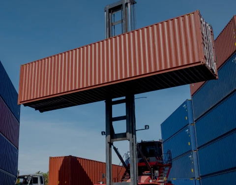
| Logistics phụ tùng thay thế | Thời gian giao hàng từ châu Âu là 8–12 tuần | Chọn các nhà cung cấp có kho hàng tại Ấn Độ; đặt hàng các bộ phớt cơ khí, bộ vòng bi và bộ nam châm tại địa phương |
Đây không phải là những lo ngại mang tính lý thuyết. Việc xây dựng các nhà máy theo mô hình PLI tại Gujarat (Vapi, Vadodara, Ankleshwar, Dahej, Jhagadia), Telangana (cụm Hyderabad-Sangareddy), Andhra Pradesh (Visakhapatnam-Atchutapuram) và Tamil Nadu (Cuddalore) đang diễn ra với tiến độ vận hành gấp rút theo các khung phát triển khu công nghiệp dược phẩm. Các nhà sản xuất thiết bị dược phẩm OEM và nhà thầu EPC của Ấn Độ ngày càng ưu tiên các nhà cung cấp có kinh nghiệm thực hiện dự án tại Ấn Độ đã được chứng minh thay vì các nhà cung cấp quốc tế không có hỗ trợ vận hành tại địa phương.
9. Danh mục máy bơm dược phẩm Aulank dành cho các nhà máy tại Ấn Độ
Từ năm 2018, chúng tôi đã cung cấp các loại bơm truyền động từ tính và bơm động cơ kín cho các dự án dược phẩm và hóa chất tinh khiết tại Ấn Độ, bao gồm việc giao hàng trực tiếp cho các nhà tích hợp nhà máy sản xuất hoạt chất dược phẩm (API) tại Vapi-Vadodara, các nhà sản xuất thiết bị OEM cho nhà máy bào chế tại Mumbai-Pune, cũng như các nhà sản xuất chất điện giải và sản phẩm trung gian tại Hyderabad và Visakhapatnam. Ma trận danh mục sản phẩm mà chúng tôi thường khuyến nghị cho các nhà máy API hoặc nhà máy bào chế:
| Trạm | Điều khoản dịch vụ | Máy bơm Aulank được khuyến nghị |
| Hệ thống tuần hoàn trong lò phản ứng API (axit/halogen hóa) | pH < 2, 60–120 °C, 3–6 bar | AMC-F - Hệ thống truyền động từ tính có lớp lót PTFE |
| Hệ thống tuần hoàn lò phản ứng API (trung tính) | pH 5–9, 40–100 °C, 3–6 bar | MDH hoặc MDS – Máy tạo xoáy từ tính bằng thép không gỉ |
| Vận chuyển dung môi số lượng lớn | Methanol, IPA, acetone, DMF trong Khu vực PESO 1/2 | MDW với động cơ chống cháy nổ được chứng nhận PESO |
| Chuyển giao dung môi clo hóa | DCM, cloroform, EDC | AMC-F - Hệ thống truyền động từ tính có lớp lót PTFE |
| Áo khoác lò phản ứng dầu nhiệt | 180–300 °C Therminol hoặc Marlotherm | Bơm dầu nhiệt nhiệt độ cao kết hợp WRY-H |
| Hệ thống làm mát bằng dung dịch muối/glycol làm lạnh | −30 đến +10 °C, 30–50% hỗn hợp glycol-nước | MDS hoặc MDK – dòng xoáy truyền động từ tính |
| Hệ thống ống dẫn nước tinh khiết / WFI | 70–85 °C, ứng dụng vệ sinh, ASME BPE | MDH hoặc MDS có xử lý điện phân và khớp nối Tri-Clamp tiêu chuẩn vệ sinh |
| Hệ thống tuần hoàn làm sạch CIP | 1–2% NaOH/HNO₃, 75–85 °C | Máy tạo xoáy từ tính bằng thép không gỉ MDS |
| Công thức liều lượng vi lượng | 0,1–5 lít/phút, độ chính xác ±0,5% | Bơm bánh răng từ tính siêu nhỏ MDC-M |
| Công thức liều lượng tầm trung | 5–50 lít/phút, độ chính xác ±1% | Bơm bánh răng từ tính MDC-K |
| Dây chuyền đóng gói vô trùng | 50–200 lít/phút, vô trùng | Bơm bánh răng từ tính cỡ trung bình đến lớn MDC-X |
| Thu hồi dung môi / nước ngưng tụ | Dung môi thu hồi, 50–80 °C, liên tục | PWH/PWD/PWM - Máy tạo dòng xoáy dạng hộp |
Giá trị cụ thể mà các nhà sản xuất OEM dược phẩm Ấn Độ nhận được từ chúng tôi:
● Các biến thể động cơ được chứng nhận PESO hiện có sẵn trong các dòng sản phẩm MDH, MDW, MDS, MDC và AMC-F, dành cho các ứng dụng sử dụng dung môi ở Khu vực 1 và Khu vực 2.
● Các cuộn dây động cơ được thiết kế chịu được khí hậu nhiệt đới và vỏ hộp đấu nối đạt tiêu chuẩn IP65 được trang bị mặc định cho các lô hàng vận chuyển đến các khu vực có mùa mưa.
● Các tùy chọn về tiêu chuẩn vệ sinh bao gồm xử lý điện phân theo tiêu chuẩn ASME BPE, kết nối Tri-Clamp và khả năng truy xuất nguồn gốc vật liệu đầy đủ kèm theo chứng chỉ kiểm tra của nhà máy để phục vụ cho hồ sơ tuân thủ cGMP.
● Tùy chỉnh điện áp và tần số — 415 V (dung sai ±15%), 50 Hz, ba pha theo tiêu chuẩn của Ấn Độ; các tùy chọn một pha 230 V và dòng điện một chiều (DC) dành cho các ứng dụng trong phòng thí nghiệm và nhà máy thí điểm.
● Kiểm soát chất lượng được chứng nhận — ISO 9001, TÜV CE đối với máy bơm xoáy truyền động từ tính, hồ sơ kiểm tra các thông số riêng lẻ, khả năng truy xuất nguồn gốc vật liệu đầy đủ, phù hợp với các cuộc kiểm toán của FDA và WHO-GMP. Để tìm hiểu thêm về hơn 17 năm kinh nghiệm trong lĩnh vực thiết kế bơm truyền động từ tính và 10 công nghệ cốt lõi đằng sau dòng sản phẩm này, bao gồm cấu trúc truyền động nam châm vĩnh cửu đồng bộ, khách hàng có thể tham khảo tài liệu về khả năng chống ăn mòn trên trang giải pháp bơm chống ăn mòn và các chi tiết kỹ thuật về ngăn rò rỉ trên trang giải pháp bơm chống rò rỉ của chúng tôi.
Nếu quý vị đang tìm kiếm các loại bơm cho một nhà máy sản xuất dược phẩm nguyên liệu được tài trợ bởi PLI, một cơ sở sản xuất công thức mới, hoặc dự án nâng cấp dây chuyền sản xuất hoạt chất dược phẩm (API) hiện có, vui lòng gửi cho chúng tôi các điều kiện vận hành chi tiết theo từng trạm. Chúng tôi sẽ gửi lại danh mục các loại bơm được đề xuất kèm theo các tài liệu tham chiếu chứng chỉ PESO, báo cáo thử nghiệm vật liệu và báo giá trong vòng hai ngày làm việc.
Tìm hiểu về giải pháp bơm dược phẩm được thiết kế riêng cho nhà máy của bạn tại Ấn Độ
Cho dù quý vị là đội ngũ kỹ sư nhà máy sản xuất hoạt chất dược phẩm (API) tại Vapi hay Hyderabad, nhà sản xuất thiết bị pha chế (OEM) tại Mumbai hay Pune, một nhà sản xuất bồn phản ứng lót thủy tinh tại Ahmedabad, hay một nhà thầu EPC đang triển khai khu công nghiệp dược phẩm nguyên liệu được tài trợ bởi PLI — đội ngũ kỹ thuật của chúng tôi có thể lựa chọn kiến trúc bơm truyền động từ tính hoặc bơm động cơ hộp phù hợp cho từng trạm xử lý chất lỏng trong thiết kế của quý vị.
Hãy liên hệ với đội ngũ của chúng tôi: Liên hệ với Aulank | WhatsApp: +86 13773157367 | Email: info@aulankpump.com
Xem các trang sản phẩm và giải pháp liên quan: