



Ask five vendors where air cooling stops and you will get five numbers: 15, 20, 40, 50, even 80 kW per rack. Every one of them is defensible, because each describes a different boundary: a legacy room average, a contained aisle, a close-coupled product, or an active rear door. The confusion disappears once the physics are laid out, because the limit is a moving threshold set by three measurable mechanisms, and all three trace back to one equation. This guide works through the physics of the air wall: why convective heat transfer caps air cooling, where the practical thresholds sit for each air architecture, what changed on the chip side to make the question urgent, and what engineering actually crosses the wall. The answer matters to anyone specifying cooling for AI hardware, because choosing an architecture means choosing a side of the threshold.
The One Equation Behind Every Cooling Decision
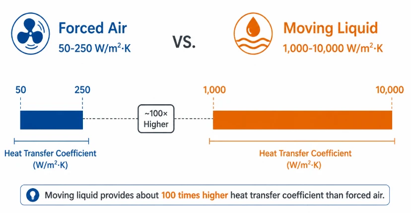
All convective cooling, air or liquid, obeys Newton's law of cooling: Q = h × A × ΔT. The heat removed equals the convective heat transfer coefficient times surface area times the temperature difference between surface and fluid. Of the three terms, the surface area of a chip package is fixed by its footprint, and the allowable temperature difference is capped by the silicon's thermal limit, leaving the coefficient h as the only term engineering can move by orders of magnitude. Forced air delivers h values of roughly 50 to 250 W/m²·K. Moving liquid delivers 1,000 to 10,000 W/m²·K. Switching the working fluid from air to water multiplies convective capacity by a factor near 100 before any other design change.
The transport side shows the same gap. Per unit volume, water carries roughly 3,500 times the heat of air for the same temperature rise. Moving 40 kW out of a rack with air at a 15°C temperature rise demands about 2.5 cubic meters of air per second, near 8,000 CFM, through a 600 mm wide cabinet. The same load in water needs a few liters per minute through a finger-sized hose. Air cooling engineering is the art of stretching these two numbers; liquid cooling starts where stretching stops paying.
Where the Air Wall Actually Sits
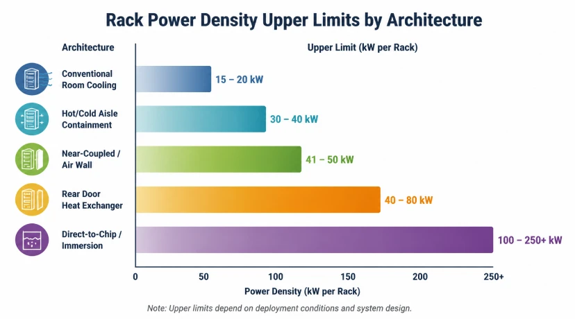
The practical ceiling depends on the air architecture, which is why published limits scatter:
| Architecture | Practical ceiling | What sets the boundary |
|---|---|---|
| Conventional room cooling (CRAC/CRAH) | 15 to 20 kW per rack | Long shared air path, mixing losses, room-average design |
| Contained hot/cold aisle | 30 to 40 kW per rack | Airflow volume, fan energy, acoustic limits |
| Close-coupled and fan-wall designs | 41 to 50 kW per rack | Short air path, aggressive CFM, supply temperature control |
| Rear-door heat exchanger (liquid coil) | 40 to 80 kW per rack | Heat transport already liquid; air only inside the rack |
| Direct-to-chip and immersion | 100 to 250+ kW per rack | Convective coefficient moved to liquid values |
The rear-door row explains most of the confusion: a rack with an active liquid-cooled door keeps air-cooled servers yet has already crossed to liquid for heat transport. The honest statement of the air wall is that unassisted air transport saturates around 35 to 40 kW per rack in well-engineered containment, and every architecture above that figure has liquid somewhere in the heat path.
Three Mechanisms That Enforce the Wall
Airflow volume becomes physically impractical
Required airflow scales linearly with heat load at fixed temperature rise. The 8,000 CFM that a 40 kW rack needs already strains server inlet areas of a few square inches; at 100 kW the figure approaches 20,000 CFM, air velocity through the chassis exceeds what any enclosure sustains, and documented failures show how thin the margin is: one recorded incident saw 250 racks at just 6 kW each climb from 72°F to over 90°F in 75 seconds after a cooling interruption.
Fan energy follows a cube law
Fan power scales with the cube of airflow. A 10 percent increase in air volume demands roughly 33 percent more fan power, and the servers' own fans join the facility fans in the bill. Air-cooled halls at high density watch cooling overhead climb toward a third of total facility energy, with PUE degrading past 1.5, while the acoustic environment in hot aisles reaches 85 to 95 dBA, into hearing-protection territory.
Thermal gradients defeat uniformity
Even when total airflow suffices, the vertical gradient inside a dense rack does not: servers at the top of a 40 kW rack ingest measurably warmer air than servers at the bottom, and component aging follows temperature. Semiconductor reliability follows the ten-degree rule, where a 10°C rise roughly halves component life, and field statistics attribute about 55 percent of electronic failures to excessive or uneven temperature. The wall is a reliability wall as much as a capacity wall.
The Chip Side Left Air Behind Years Ago
The rack view understates the problem, because the binding constraint forms at the silicon. Forced air cooling tops out near 1.6 W/cm² of heat flux at the device surface. Current accelerators passed that figure several generations ago: the H100 class runs near 86 W/cm² at 700 W per package, the B200 doubles the package power to 1,000 W, and the B300 roadmap reaches 1,400 W, with heat concentrating on chiplet zones far smaller than the package. No arrangement of heatsinks and fans closes a gap of that width; the convective coefficient must change, which means liquid at the chip surface. Cold plates accomplish this by bringing microchannel flow within millimeters of the silicon, and the resulting thermal resistance of 0.02 to 0.10°C/W sits an order of magnitude beyond anything air delivers.
What the Efficiency Ledger Looks Like After Crossing
The operational case compounds the physics case. Air-cooled facilities typically run PUE between 1.4 and 1.8, with well-optimized containment reaching 1.2 to 1.3; liquid-cooled halls hold 1.05 to 1.15 largely independent of climate. Reliability moves with temperature: eliminating server fans removes a component class responsible for a large share of field failures, and documented deployments report mean time between failures extending from roughly 40,000 to 65,000 hours, with hard drives gaining about 20 percent service life at the lower, steadier temperatures liquid maintains. Acoustics follow the same direction, from 85 to 95 dBA hot aisles down toward conversational levels. Each line of the ledger traces back to the same source: the convective coefficient changed, and everything downstream of heat removal got easier.
Crossing the Wall: What Changes and What Stays
The transition path runs through recognizable stages. Rear-door heat exchangers convert an existing air hall to liquid transport without touching the servers, serving 40 to 80 kW per rack while the load base justifies more. Direct-to-chip cold plates take over from 35 kW upward and dominate current AI deployments, holding standard chassis and service workflows while a coolant distribution unit manages the loop; the architecture and its components are covered in what a coolant distribution unit is and how it works. Immersion removes air from the heat path entirely for the highest densities. What stays constant across all three is the need for reliable liquid circulation, and that is where the engineering conversation turns to pumps.
Once You Cross, the Pump Carries the Risk
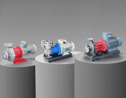
Liquid cooling trades airflow limits for hydraulic requirements: stable pressure against cold plate microchannel resistance, continuous variable-speed duty, glycol coolant chemistry, and absolute leak integrity above live equipment. The pump becomes the component that converts the physics advantage into daily reliability. Seal-less magnetic drive circulation pumps with stainless wetted paths, such as the MDW series, answer the zero-leakage and low-flow stability requirements directly, and the full selection framework appears in the AI data center liquid cooling pump selection guide.
Aulank Pump manufactures seal-less vortex magnetic drive pumps for data center liquid cooling loops, rated for water-glycol media across −196°C to +400°C with helium leak-tested containment. If your project is crossing the air wall, send us the loop flow and pressure drop data and our engineering team will return a matched pump with the sizing calculation. Contact us to discuss your liquid cooling project.