


In heavy industrial processing, fluid handling systems do not operate under static conditions. For fluid systems engineers and plant maintenance directors, scheduling service intervals for processing machinery requires a deep understanding of fluid rheology, mechanical wear, and material deterioration. When systems handle aggressive acids, highly reactive alkalis, or high-temperature solvents, components degrade at predictable intervals.
Waiting for a chemical fluid transport system to experience an unplanned breakdown before performing maintenance risks operator safety, environmental contamination, and high production losses. This technical overview provides an engineering framework for evaluating how often to change chemical pump parts, structuring preventive service intervals, and selecting materials to extend component lifespans in demanding chemical applications.

Defining Component Lifecycle Factors in Highly Corrosive Fluid Systems
The service life of internal components in a chemical delivery system depends on several physical and operational factors. A single calendar-based maintenance schedule cannot accurately account for variations in chemical processing environments.
To establish a highly effective preventive maintenance plan, fluid handling engineers must analyze four core operational variables:
● Chemical Aggressiveness and Concentration: Highly concentrated inorganic acids (such as 98% sulfuric acid) or strong oxidative compounds accelerate chemical attack on metal and polymer surfaces. This leads to micro-pitting, stress corrosion cracking, and rapid elastomeric swelling.
● Thermodynamic Thresholds: Running systems at high temperatures lowers fluid viscosity, increases vapor pressure, and accelerates chemical reaction rates on exposed surfaces. This elevates the risk of localized cavitation damage and rapid seal wear.
● Particulate Contamination: The presence of micro-abrasive particles or crystalline chemical scale acts like an internal abrasive grinding fluid. This quickly erodes impellers, scores shaft sleeves, and clogs close-clearance internal channels.
● System Duty Cycle: Continuously operating systems (24/7 manufacturing) accumulate mechanical strain and run-time hours much faster than intermittent or batch-processing configurations. This requires shorter, more frequent inspection and service schedules.

Dynamic Wear Components: The Critical Lifespan Schedules
Dynamic components face continuous frictional force, hydraulic pressure variations, and direct contact with aggressive chemical fluids. Tracking these parts based on actual operational hours or precise timeframes is crucial for preventing unexpected breakdowns.
Elastomeric O-Rings, Gaskets, and Static Seals
● Standard Replacement Window: Every 3 to 6 months.
● Technical Insights: Elastomers are highly susceptible to chemical swelling, hardening, and loss of compression set when exposed to aggressive process chemistry. For critical zero-leakage safety boundaries, technicians must inspect static seals during every routine fluid loop service. If a seal shows any signs of flattening or hardening, it should be replaced immediately to avoid a catastrophic leak.
Dynamic Mechanical Seal Assemblies
● Standard Replacement Window: Every 6 to 12 months (or every 3,000 to 6,000 run-time hours).
● Technical Insights: Mechanical seal faces (often built from silicon carbide or tungsten carbide) depend on a micro-thin layer of process fluid to provide lubrication across their mating surfaces. Any brief dry-running condition or pressure spike causes rapid heat generation, face checking, and seal failure.
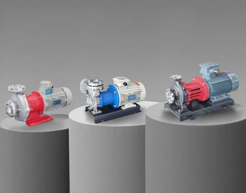
● Sealless Alternative: To bypass the maintenance costs and failure risks of traditional dynamic seals, chemical processing operations are increasingly moving to sealless Magnetic Drive Centrifugal Pumps or hermetically sealed Canned Motor Pumps. These designs replace dynamic seals with static isolation containment shells, eliminating the primary path for process fluid leaks.
Rotating Impellers and Internal Diffusers
● Standard Replacement Window: Every 12 to 24 months.
● Technical Insights: Impeller wear rates vary based on fluid velocity and the presence of entrained solids or micro-abrasives. In clean, low-viscosity processes, a high-quality alloy or fluoroplastic-lined impeller can maintain its hydraulic profile for over two years. However, in abrasive slurry services or systems experiencing suction cavitation, the trailing edges of the blades can erode rapidly, leading to a noticeable drop in flow rate and system pressure.

Stationary Wear Components: Managing Secondary Point Vulnerabilities
Stationary components do not move within the hydraulic stream, but they are subject to continuous system pressures, fluid turbulence, and environmental stress.
Internal Shaft Sleeves and Bushings
● Standard Replacement Window: Every 12 to 18 months.
● Technical Insights: In sealless magnetic drive structures, the internal sleeve bearings (frequently made from alpha sintered silicon carbide) are continuously lubricated by the process liquid itself. If the intake line experiences fluid starvations or entrained gas pockets, these close-clearance bearings can suffer severe thermal shock and micro-fractures, requiring an immediate rebuild of the internal wet-end assembly.
Pump Casings and Volute Linings
● Standard Replacement Window: Every 36 to 60 months.
● Technical Insights: Metal casings (such as CF8M stainless steel or Hastelloy) degrade slowly if the metallurgy matches the process chemistry. However, in aggressive acid services using fluoroplastic-lined pumps (PTFE/PFA), the liner must be regularly inspected for deep gouges, chemical permeation, or structural vacuum collapses caused by high negative pressures in the intake piping.

Establishing a Preventive Industrial Fluid System Maintenance Checklist
Industrial operations should move away from reactive repair practices and adopt a structured, multi-tier preventive maintenance plan to protect critical equipment.
An optimized industrial service protocol should follow this structured execution schedule:
Daily Performance Inspections
1. Visual Leak Audits: Inspect all structural connections, outer containment shells, and drain ports for fluid weeping or crystal buildup.
2. Acoustic and Temperature Monitoring: Listen for high-pitched metal clicking (indicative of cavitation or bearing wear) and measure the surface temperature of the bearing housing using an infrared thermometer.
Monthly System Realignments
1. Shaft Alignment Verification: Use laser alignment tools to check the coupling alignment between the pump and electric motor, ensuring tolerances stay within manufacturer specifications.
2. Lubrication Maintenance: Check the oil levels and fluid quality in oil-bath bearing frames, or inject high-temperature grease into greased bearings to prevent friction-induced heat wear.
Quarterly Internal Components Inspections
1. Suction Strainer Maintenance: Clean and flush the intake strainers to remove trapped debris, ensuring the system maintains adequate Net Positive Suction Head Available ($NPSH_a$).
2. Valve Performance Audits: Check the seating and operation of system isolation valves, check valves, and pressure relief safety valves to maintain stable directional control.
Material Matching Framework: Mitigating Chemical Degradation Rates
The operational lifespan of any fluid processing component is fundamentally tied to the structural compatibility of its liquid-end materials. Selecting materials with higher chemical resistance reduces part replacement frequency and lowers the total cost of ownership.
| Base Metallurgy / Polymer | Chemical Resistance Spectrum | Target Industrial Use Case | Expected Service Life (Clean Media) |
| 316L / CF8M Stainless Steel | Excellent for organic solvents, alcohols, light alkaline solutions, and low-concentration acids. | Semiconductor chemical distribution, bulk solvent transfer loops. | 3 to 5 Years (Casing) / 12–18 Months (Wear Parts) |
| PFA / F46 Fluoroplastic Lining | Complete resistance to highly concentrated inorganic mineral acids (Hydrochloric, Nitric, Sulfuric) and aggressive caustics. | Acid pickling lines, raw chemical manufacturing, industrial wastewater treatment. | 2 to 4 Years (Liner) / 6–12 Months (Internal Seals) |
| Hastelloy C / Titanium Alloys | Superior resistance to high-temperature chlorides, oxidizing salt solutions, and severe chemical mixtures. | Heavy petrochemical refining reactors, high-stress specialized chemical synthesis. | 5+ Years (Casing) / 18–24 Months (Internal Wear Components) |
Mitigating Suction Cavitation and Fluid Dynamics Pitfalls
Many premature component failures are caused by improper hydraulic system integration rather than basic material wear. Cavitation is a major driver of early component failure in chemical processing systems.
When local static pressure inside the pump falls below the liquid's vapor pressure, vapor bubbles form in the fluid stream. As these bubbles enter high-pressure areas within the impeller, they violently collapse, generating localized high-energy micro-jets with calculated impact pressures up to 10,000 Bar. This continuous mechanical impact micro-fractures metals and plastics alike, quickly destroying impellers and shattering silicon carbide bearings.
To prevent cavitation-induced component wear, system designs should implement these engineering practices:
1. Increase Intake Pipe Sizing: The suction line should be at least one size larger than the pump's inlet flange to minimize friction head losses.
2. Maintain a Straight Suction Run: Install a straight run of unobstructed pipe with a length equal to at least five times the pipe diameter right before the pump inlet to deliver a smooth, uniform velocity profile.
3. Continuous Digital Power Monitoring: Integrate a digital power monitor into the motor control panel. This system tracks real-time power draw and cuts motor power instantly if the fluid stream is interrupted, protecting sealless magnetic drive bearings from dry-running damage.
The global regulatory standard for managing these hazards is detailed in the Hydraulic Institute Standards (HI 9.6.1), which defines the precise metrics for matching fluid dynamics to machinery configurations.
