


Pumping flammable liquids with standard equipment converts a routine transfer operation into an ignition source waiting for fuel. Solvents such as acetone, toluene, MEK, and ethanol release vapors that form explosive mixtures with air at concentrations achievable in any filling station, reactor room, or tank farm. A single arc from a motor winding, a hot bearing surface, or a static discharge from an ungrounded casing is sufficient to ignite that mixture. Explosion-proof pumps eliminate or contain these ignition sources through certified motor protection concepts, antistatic construction, and seal architectures that keep flammable fluid and vapor inside the pressure boundary. This specification guide explains how to classify the installation zone, decode Ex markings, and match pump engineering to the actual hazard, based on ATEX Directive 2014/34/EU, IECEx, and NEC frameworks.
What Makes a Pump Explosion-Proof
An explosion-proof pump is defined by its ability to prevent ignition of the surrounding atmosphere, not by the absence of sparks inside the machine. The engineering objective is to control every credible ignition source that the pump can present to an explosive atmosphere. These sources fall into four categories:
- Electrical ignition: Arcs and sparks from motor windings, terminals, switches, and cable entries. Protection concepts such as flameproof enclosures (Ex d) contain an internal ignition and cool escaping gases through engineered flame paths before they reach the hazardous area.
- Hot surfaces: Bearings, shaft seals, and motor housings can exceed the autoignition temperature of the vapor present. Certified equipment carries a temperature class (T1 through T6) guaranteeing that no accessible surface exceeds the stated limit, even under fault conditions.
- Static electricity: Fluid flow, splashing, and particle movement accumulate charge on the pump casing and connected piping. Conductive or antistatic wetted materials and a verified equipotential ground connection discharge this energy continuously instead of allowing a sudden spark.
- Mechanical friction: Rubbing contact between rotating and stationary parts during dry running or bearing failure generates both heat and sparking. Seal-less designs and dry-run protection devices address this failure mode directly.
Classifying the Hazardous Area Before Selecting Equipment
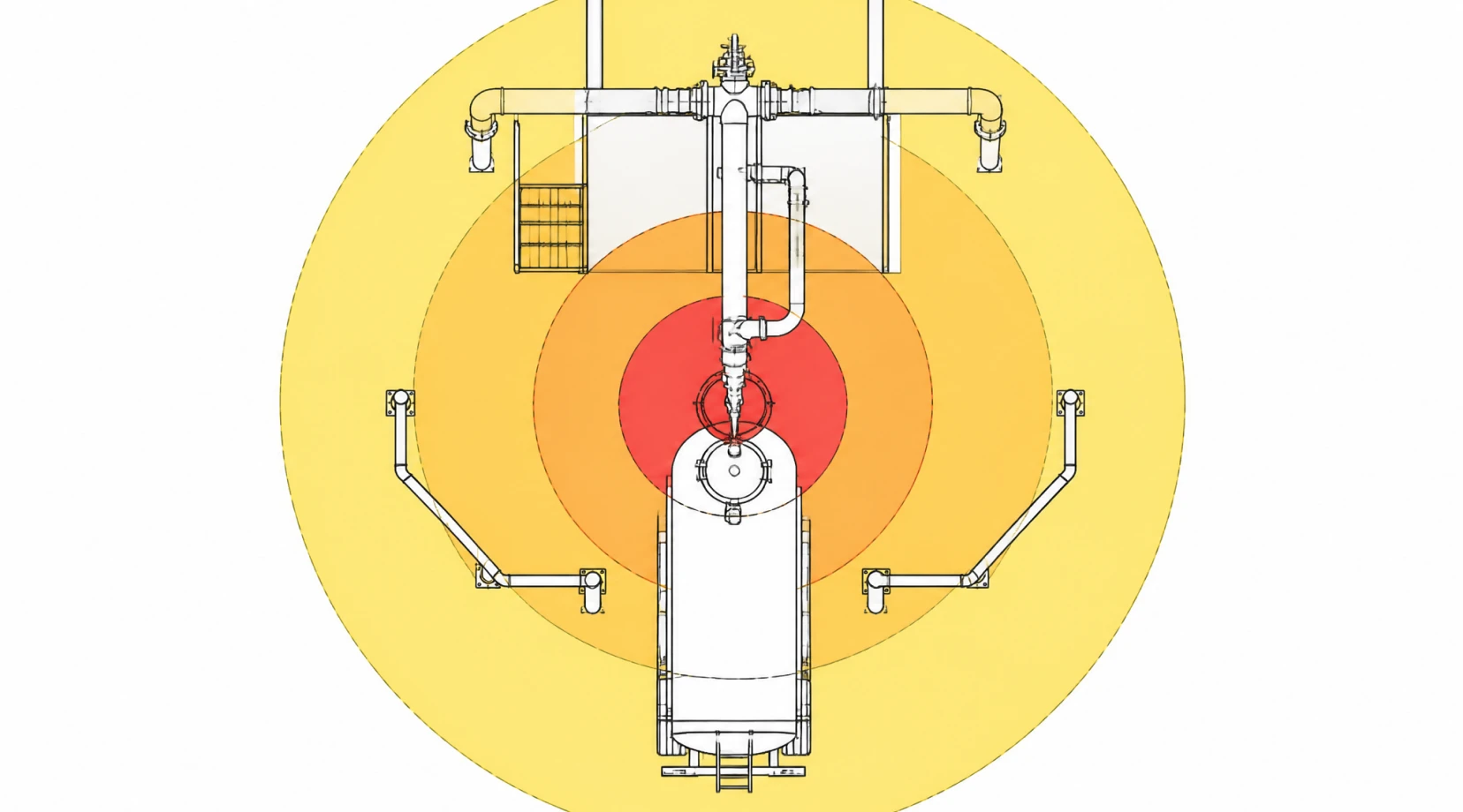
Pump selection starts with the zone classification of the installation point, which the plant operator defines under ATEX Directive 1999/92/EC (or IEC 60079-10-1 outside the EU) through a documented assessment of vapor release sources and ventilation. The classification describes how often an explosive atmosphere is expected:
| Zone | Explosive atmosphere presence | Required equipment category (gas) |
|---|---|---|
| Zone 0 | Continuously or for long periods | Category 1G (highest protection, two independent fault tolerances) |
| Zone 1 | Occasionally during normal operation | Category 2G (protection under single-fault conditions) |
| Zone 2 | Unlikely, and only briefly if it occurs | Category 3G (protection during normal operation) |
Typical solvent transfer points in chemical and pharmaceutical plants fall into Zone 1 at the filling connection and Zone 2 across the surrounding room. Pump seal leakage points are commonly classified as Zone 2, which is one reason leakage elimination changes the compliance equation. Dust atmospheres follow the same logic under Zones 20, 21, and 22. Equipment certified for a higher category is always acceptable in a lower zone; the reverse is a compliance violation and an audit failure.
Gas Groups and Temperature Classes
Two fluid-specific parameters narrow the specification further. The gas group reflects how easily the vapor ignites and propagates flame: IIA covers propane, acetone, ethanol, and gasoline; IIB covers ethylene and diethyl ether; IIC covers hydrogen, acetylene, and carbon disulfide. Equipment marked IIC satisfies all lower groups. The temperature class states the maximum surface temperature of the equipment and must sit below the ignition temperature of the vapor, with T6 (85 °C) the most restrictive and T1 (450 °C) the least. Applying the strictest substance present in the area, rather than the most common one, is the correct engineering practice; audit records show that equipment marked IIA operating in IIB or IIC service is among the most frequent non-conformities in chemical plant inspections.
Decoding the Ex Marking on a Pump
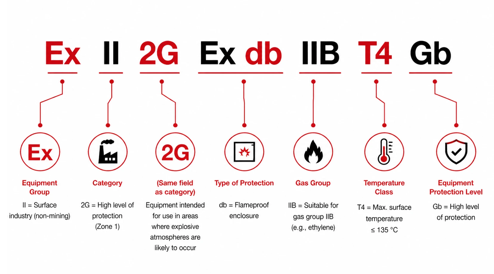
The ATEX label on a certified pump reads as a single string that experienced buyers verify line by line against the zone assessment. A typical marking such as Ex II 2G Ex db IIB T4 Gb decodes as follows: II indicates equipment group for surface industries; 2G indicates category 2 for gas atmospheres, suitable for Zone 1; Ex db identifies the flameproof protection concept applied to the motor; IIB is the gas group; T4 limits surface temperature to 135 °C; Gb is the equipment protection level. Any mismatch between this string and the zone documentation invalidates the installation regardless of build quality. North American projects follow the same logic under NEC Article 500 or the Zone-based Article 505.
Pump Architecture Choices for Flammable Service
Seal-Less Magnetic Drive Pumps
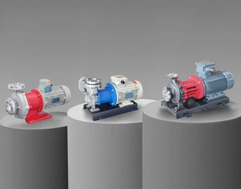
The shaft seal is the statistically dominant leakage path on any rotating pump, and in flammable service every leak is a vapor release inside a classified zone. Magnetic drive pumps transmit torque through a containment shell with no dynamic seal, so the flammable fluid stays inside a hermetically closed pressure boundary. This architecture removes the leakage-driven ignition scenario entirely and eliminates the seal support systems, flush plans, and emission monitoring that mechanical seal pumps require under LDAR programs. If you are dealing with critical fluids, understanding the differences in seal-less mechanisms is crucial for longevity. Aulank magnetic drive pumps, such as the MDH series and the AMC-L process line, are configured with explosion-proof motors and stainless steel wetted parts for solvent transfer. For broader model coverage, refer to our comprehensive selection guide.
Air-Operated Diaphragm Pumps
AODD pumps carry no electrical component and present no electrical ignition source, which makes them a practical choice for drum emptying and intermittent transfer in Zone 1. The limitation is static control: the pump body, conductive hoses, and fittings must all be bonded to a verified ground, and diaphragm materials must be specified as conductive grades.
Canned Motor Pumps
Canned motor pumps integrate motor and hydraulic in one sealed housing and suit continuous process duty with toxic or flammable fluids. The trade-off is that the motor rotor operates in the pumped fluid, which restricts the technology to clean, lubricating liquids and requires bearing wear monitoring as a maintenance priority.
Engineering Controls Beyond the Pump Nameplate
Certification on the pump does not make the installation compliant. Four field-level controls determine whether the certified protection survives operation:
- Equipotential grounding: Pump casing, motor frame, piping, and adjacent vessels connect to a common ground network. Grounding continuity requires periodic verification, because corrosion and repainting silently break connections.
- Dry-run protection: A magnetic drive pump running dry overheats the bearing assembly within minutes and can push surface temperatures past the T-class limit. PTC thermistors in the motor windings and flow or current monitoring on the discharge side are standard safeguards.
- Cable entries and glands: An incorrectly selected or installed cable gland voids the flameproof integrity of the motor enclosure. Glands must match the Ex concept and cable diameter.
- Maintenance discipline: Flame paths on Ex d enclosures are machined to precise tolerances. Damaged flange faces, substitute fasteners, or non-certified spare parts destroy the protection concept.
A Selection Workflow That Survives Audits
A defensible specification process for flammable liquid pumps follows a fixed sequence:
- Obtain the area classification document and identify the exact zone.
- List every flammable substance present and select the strictest gas group and lowest ignition temperature.
- Define the hydraulic duty and shortlist pump architectures, weighting seal-less designs.
- Verify the full Ex marking of the shortlisted pump against steps one and two.
- Specify the installation controls: grounding scheme, dry-run protection, and monitoring.
- File all conformity declarations with the plant safety documentation.
Ensuring Compliance in the Field
Three errors recur across solvent handling projects. The first is selecting on the motor alone: a flameproof motor bolted to a leaking mechanical seal still presents a hazard. The second is ignoring the temperature class interaction with the actual process temperature. The third is treating Zone 2 as a "low risk" area that requires no specialized equipment, which frequently causes compliance failures during inspections. If you are handling challenging fluids, reviewing proven zero-leakage strategies will further secure your operation.
Aulank Pump manufactures vortex, centrifugal, and positive displacement units with explosion-proof configurations and seal-less magnetic drive options for flammable transfer across the chemical and energy sectors. Share your zone classification with our engineering team, and we will return a matched pump configuration with the full certification package. Contact us for a technical review of your hazardous area application.