


No one can pick the right pump until the job is defined in numbers. “Move some solvent to the day tank” is not a specification — a pump curve is. Before a centrifugal or vortex pump can be selected, three quantities have to be worked out: how much flow the process needs, how much head the pump must generate to deliver that flow, and how much suction pressure is available so the pump does not cavitate. Get those three right and selection is straightforward. Get the head wrong, or skip the suction check, and you end up with a pump that runs hot, cavitates, or never makes its flow.
This walks through the calculation the way we do it when a customer sends us an enquiry — flow first, then total dynamic head, then NPSH, then the power that sets the motor — with the formulas, a full worked example you can copy, and the sizing mistakes that cause most of the trouble. The method here is for rotodynamic pumps (centrifugal and vortex); positive-displacement pumps are sized on a different basis, noted at the end.
The Three Numbers That Define the Duty Point
A pump's duty point is where it has to operate, and it takes three inputs to pin it down:
● Flow rate (Q) — the volume the process needs per unit time, in m³/h or L/min (or GPM).
● Total dynamic head (TDH, or H) — the total energy the pump must add to move that flow, expressed as a height of liquid, in metres (or feet).
● Net positive suction head available (NPSHa) — how much absolute pressure is available at the pump inlet above the fluid's vapour pressure, which decides whether the pump cavitates.
Flow and head together fix the point on the pump curve. NPSHa is checked against the pump's NPSH required to make sure the chosen pump will actually run there without cavitating. Power follows from flow and head, and sets the motor. Work them in that order.
Flow Rate: Start with the Process
Flow is usually set by the process, not the pump. A heat-exchanger loop needs a certain circulation rate to carry the heat; a filling line needs to fill a vessel in a set time; a transfer duty needs to empty a tanker within a shift. Work out the rate the process actually requires, and use the peak demand, not the average, if the two differ. One caution: do not pad the flow “to be safe.” An oversized flow figure drives up head, power, and pump size, and lands the pump on the wrong part of its curve. Size for the real requirement and use a variable-speed drive if the demand varies.
Total Dynamic Head: the Number People Get Wrong
Total dynamic head is the most common place pump sizing goes wrong, because people use the static lift alone and forget the rest. The full picture adds four parts:
TDH = static head + friction head + pressure head + velocity head
● Static head — the vertical elevation difference between the suction liquid surface and the discharge liquid surface. This is the part most people remember.
● Friction head — the energy lost to friction in the suction and discharge piping, valves, and fittings. It rises with the square of flow, so it grows fast in long or undersized lines, and you read it off friction-loss charts or calculate it with the Darcy-Weisbach or Hazen-Williams method for the pipe size, length, and fittings.
● Pressure head — only if the suction or discharge vessel is pressurized or under vacuum. Convert the pressure difference to a height of liquid: head in metres = pressure (kPa) ÷ (ρ × 9.81). For open tanks at both ends, this term is zero.
● Velocity head — the kinetic energy of the moving fluid, V²÷2g. At normal pipe velocities it is small, and for most sizing it is left out.
Add the parts and you have the head the pump must generate at the required flow. The single biggest sizing error is using static head only: a pump sized on the 16 m lift in the example below, ignoring the 5 m of friction, would fall about 5 m short of head and never reach its design flow.
A Worked Example, End to End
Take a real-shaped duty: transfer 20 m³/h of an organic solvent, specific gravity 0.87, vapour pressure about 12 kPa at 30°C, at a site near sea level (atmospheric pressure 101 kPa). The suction tank surface sits 2 m above the pump (flooded suction); the discharge tank surface is 18 m above the pump; both tanks are open to atmosphere. Suction-line friction is 0.6 m and discharge-line friction is 4.5 m at this flow. Here is the whole calculation:
| Quantity | Value | How |
| Required flow (Q) | 20 m³/h | Process demand |
| Static head | 16 m | Discharge surface 18 m − suction surface 2 m |
| Friction head (suction + discharge) | 5.1 m | 0.6 + 4.5, from friction charts |
| Pressure head | 0 m | Both tanks atmospheric |
| Total dynamic head (TDH) | 21.1 m | 16 + 5.1 |
| Atmospheric head (Ha) | 11.8 m | 101 kPa ÷ (870 × 9.81) |
| Suction static (Hz) | +2 m | Flooded suction, surface above pump |
| Suction friction (Hf) | 0.6 m | Suction line only |
| Vapour-pressure head (Hvp) | 1.4 m | 12 kPa ÷ (870 × 9.81) |
| NPSH available | 11.8 m | 11.8 + 2 − 0.6 − 1.4 |
| NPSH required (from curve) | 3.0 m | Manufacturer, at 20 m³/h |
| NPSH margin | 8.8 m | 11.8 − 3.0 → safe |
| Hydraulic power | 1.0 kW | 20 × 21.1 × 0.87 ÷ 367 |
| Shaft power (55% eff.) | 1.8 kW | 1.0 ÷ 0.55 |
| Motor (next size up) | 2.2 kW | Shaft power plus margin |
The duty point is 20 m³/h at 21.1 m, the suction is safe with nearly 9 m of NPSH margin, and the motor is 2.2 kW. The sections below explain the suction and power lines in more detail.
NPSH: Will the Pump Cavitate?
Cavitation is what happens when the pressure at the pump inlet drops below the fluid's vapour pressure: vapour bubbles form and then collapse violently inside the pump, eroding the impeller and bearings and shaking the whole machine. The suction check exists to prevent it. NPSH available is what the system offers at the inlet, calculated in absolute terms:
NPSHa = Ha + Hz − Hf − Hvp
Ha is the absolute pressure on the liquid surface as a head (atmospheric pressure at the site altitude); Hz is the static suction head, positive for a flooded suction and negative for a suction lift; Hf is the suction-line friction; and Hvp is the fluid's vapour pressure as a head. Two points catch people out. NPSH is always worked in absolute pressure, because vapour pressure is an absolute property, and the velocity head is not included. NPSH required (NPSHr) is the other half — it is a property of the pump, read off the manufacturer's curve at the operating flow, and it rises with flow, so always check it at the maximum flow, not the average.
The rule is NPSHa must exceed NPSHr with a margin. The Hydraulic Institute recommends NPSHa of at least 1.5 times NPSHr, or NPSHr plus roughly 0.6 to 1 m, whichever is greater. Hot fluids near their boiling point and high-altitude sites both eat into NPSHa fast, and suction lift makes it worse — practical suction lift rarely exceeds 4 to 5 m even though atmospheric pressure could in theory support about 10 m of cold water. If the margin is thin, raise the source level, shorten and widen the suction line, or cool the fluid. We go deeper into the suction side and the fixes on our preventing pump cavitation page.
Power and Motor Size
Power follows from flow and head. The hydraulic power — the useful work delivered to the fluid — is:
Hydraulic power (kW) = Q × H × SG ÷ 367, with Q in m³/h and H in metres.
That is the theoretical figure. The shaft (or absorbed) power the motor actually has to deliver is higher, because no pump is 100% efficient: shaft power = hydraulic power ÷ pump efficiency. In the example, 1.0 kW hydraulic at a 55% pump efficiency is about 1.8 kW at the shaft, so the next motor size up — 2.2 kW — gives a sensible margin. Two rules keep this honest. Size the motor for the worst case on the curve, because absorbed power rises with flow, so check it at the maximum flow the pump might see, not just the duty point. And do not over-pad: an oversized motor wastes energy every hour it runs and is a classic false economy. Pump efficiency itself is highest near the best efficiency point (BEP), which is the next thing to get right — see our industrial centrifugal pump efficiency guide.
Common Sizing Mistakes
Most sizing problems come from the same handful of shortcuts:
● Using static head only. Forgetting friction head is the classic error and leaves the pump short of its design flow.
● Padding the flow or head “to be safe.” Arbitrary safety factors push the pump off its best efficiency point, waste energy, and accelerate wear. Oversizing is the least safe choice, not the most.
● Skipping the NPSH check. A pump that looks right on flow and head will still cavitate if the suction was never verified.
● Checking NPSH and power at the duty point only. Both NPSHr and absorbed power rise with flow, so check them at the maximum flow.
● Undersizing the suction line. A thin suction line adds friction exactly where NPSH is tight.
● Operating far from BEP. Aim for a pump that runs at roughly 80–110% of its best efficiency point at the duty flow.
● Ignoring specific gravity and viscosity. A denser fluid needs more power for the same head, and a viscous fluid changes both friction and pump performance.
From Duty Point to Pump
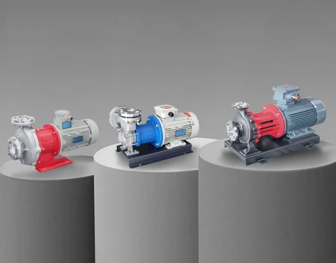
With flow, head, and NPSHa in hand, you can select the pump. The duty shape points to the type: high flow at moderate head suits a centrifugal pump; high head at low flow suits a vortex (regenerative-turbine) pump, covered in our industrial vortex pump selection guide; zero-leakage or corrosive duties point to a sealless build, covered in our magnetic drive pump selection guide. The figures above are for rotodynamic pumps. A positive-displacement pump — a gear or vane pump for viscous or precisely metered duties — is sized differently: its flow is set by displacement and speed rather than by a head-flow curve, and the system pressure is whatever the pump has to push against. Our Positive Displacement Pump Series and the Chemical Pump Series cover those options, and the full industrial pump range spans the range.
Send Us the Duty Point and We Will Size It
If you would rather have the calculation checked than done from scratch, send us the flow, the suction and discharge layout (elevations, pipe sizes and lengths, fittings), the fluid with its specific gravity, vapour pressure, and temperature, and any vessel pressures. Our engineering team will return the total dynamic head, the NPSH check, the power, and a matched pump — sealless magnetic-drive, vortex, centrifugal, or positive-displacement — for the duty.
Talk to our team: Contact Aulank | WhatsApp: +86 13773157367 | Email: info@aulankpump.com
Related reading: industrial vortex pump selection guide · magnetic drive pump selection guide