



A thermal oil system transfers heat with precision, but its continuous reliability depends entirely on the pump circulating the fluid. Pumping hot oil at 300 °C to 350 °C introduces severe physical variables: radical thermal expansion, altered fluid viscosity, and extreme mechanical stress. Standard centrifugal pumps fail rapidly under these conditions because standard elastomers melt, bearings overheat, and casing materials warp. Specifying a dedicated high-temperature thermal oil pump requires calculating exact system resistance, analyzing shifting fluid properties, and defining the correct shaft sealing mechanisms. This technical guide outlines the engineering parameters necessary for selecting a thermal fluid pump that delivers leak-free, continuous operation in industrial heat transfer applications.
The Physics of High-Temperature Pumping
Thermal fluid systems operate under the premise that liquid remains liquid even at high heat, unlike steam systems that rely on phase changes. However, sensible heat transfer demands constant, stable mass flow. When liquid temperatures exceed 250 °C, the pump casing absorbs massive thermal energy. The metallurgical components expand, which can alter internal running clearances between the impeller and the casing. Selecting the right pump involves understanding how the mechanical design accounts for this thermal growth while isolating the sensitive components—such as mechanical seals and ball bearings—from the direct heat path. Air-cooled thermal oil pumps achieve this through a specialized thermal barrier bracket that dissipates heat naturally before it reaches the critical rear assembly.
Analyzing Fluid Properties at Operating Temperature
Fluid dynamics change drastically as temperatures shift from cold startup to maximum operating heat. Three distinct fluid properties dictate pump sizing and motor selection.
Viscosity Shifts and Cold Starts
Thermal oil is highly viscous at ambient temperatures. At 20 °C, kinematic viscosity can be extremely high, causing significant resistance to flow. At an operating temperature of 300 °C, the fluid becomes almost as thin as water. The pump motor must be sized to handle the dense, viscous fluid during a cold start. If the motor is specified based only on the hot operating viscosity, it will trip or overload during initial system commissioning.
Specific Gravity and Density
Specific gravity decreases as thermal oil heats up. A fluid that weighs 880 kg/m³ at room temperature might weigh only 700 kg/m³ at 300 °C. Because centrifugal pumps transfer energy by accelerating fluid mass, pumping a lighter hot fluid requires less brake horsepower from the motor. Understanding this curve is critical to avoid oversizing the electrical components while ensuring enough power remains for cold starts.
Vapor Pressure Risks
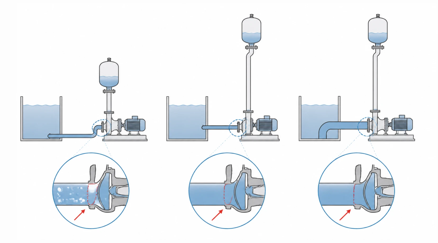
All fluids have a vapor pressure that increases with heat. If the system pressure drops below the fluid's vapor pressure at the pump inlet, the thermal oil will boil locally, creating vapor bubbles. This phase change directly leads to cavitation, which aggressively destroys impellers and vibrations that ruin mechanical seals.
Calculating Flow Rate and System Head Requirements
Accurate sizing begins with defining the thermal load of the target application, whether it is a chemical reactor jacket, a commercial oven, or a calendering roll.
● Flow Rate (Capacity): Flow requirements are derived from the heat load equation. The target kW (or BTU/hr) rating of the heater dictates how many cubic meters per hour (m³/h) of oil must circulate to maintain the target temperature drop (delta-T) across the user equipment. A smaller delta-T requires a higher flow rate.
● Total Dynamic Head (TDH): TDH represents the total resistance the pump must overcome. It is the sum of static head (elevation changes, usually negligible in closed-loop systems) and friction head. Friction head is calculated by analyzing the pipe diameter, length, elbow fittings, control valves, and the internal resistance of the heater coils and heat exchangers. Underestimating pressure drops in the heat exchanger is the most common cause of inadequate flow.
Net Positive Suction Head (NPSH) Considerations
Cavitation is lethal to hot oil pumps. Preventing it requires balancing two specific values: NPSHa (Available) and NPSHr (Required).
NPSHr is fixed by the pump geometry and is provided by the manufacturer on the pump curve. NPSHa is a characteristic of the piping system and must be calculated by the design engineer. NPSHa must always exceed NPSHr by a safety margin of at least 0.5 to 1 meter. In thermal oil systems, calculating NPSHa must factor in the elevated vapor pressure of the hot oil and the atmospheric pressure at the installation altitude. To increase NPSHa, designers usually elevate the expansion tank to provide greater static suction head, minimize suction pipe length, and use large-diameter piping to reduce friction losses on the inlet side.
Pump Construction Materials and Design
Standard cast iron (gray iron) becomes brittle at high temperatures and is unacceptable for thermal oil duty due to the risk of catastrophic cracking under thermal shock. Material selection defines safety.
| Material Type | Maximum Temp Rating | Application Suitability |
| Nodular Cast Iron (Ductile Iron) | Up to 350 °C | Standard industrial heat transfer systems. Offers excellent pressure containment and resists thermal shock far better than gray iron. |
| Cast Steel (Carbon Steel) | Up to 400 °C | High-pressure chemical and petrochemical plants. Required when compliance with specific petroleum industry safety standards (like API) is necessary. |
| Stainless Steel (304/316) | Up to 400 °C | Corrosive environments, food-grade thermal oil systems, or where external atmospheric corrosion is a severe operational risk. |
Closed impellers with optimized hydraulic channels are standard for maintaining high efficiency during bulk transfer. Internal clearances are machined slightly looser than ambient water pumps to accommodate the expected thermal expansion of the impeller diameter without galling against the volute.
Shaft Sealing Technologies for Thermal Oil
The shaft seal is the primary vulnerability in any pump. Containing a 300 °C fluid rotating at 2900 RPM requires engineered sealing solutions.
● Metal Bellows Mechanical Seals: The premier choice for hot oil. Unlike pusher-type seals that use O-rings (which degrade and harden in high heat), bellows seals use a welded metal spring structure to maintain face pressure. The faces are typically a highly durable combination of carbon graphite against silicon carbide.
● Dynamic Lip Seals with Oil Bath: A traditional, highly reliable setup uses dual high-temperature radial lip seals combined with a quench fluid or oil bath. This isolates the hot process fluid from the atmosphere while providing necessary lubrication to the sliding surfaces.
● Magnetic Drive Sealless Pumps: Where absolute zero-leakage is mandated by environmental regulations or fire codes, magnetic drive pumps eliminate the shaft penetration entirely. High-temperature samarium-cobalt magnets are utilized to prevent demagnetization at process heats up to 350 °C without requiring external cooling jackets.
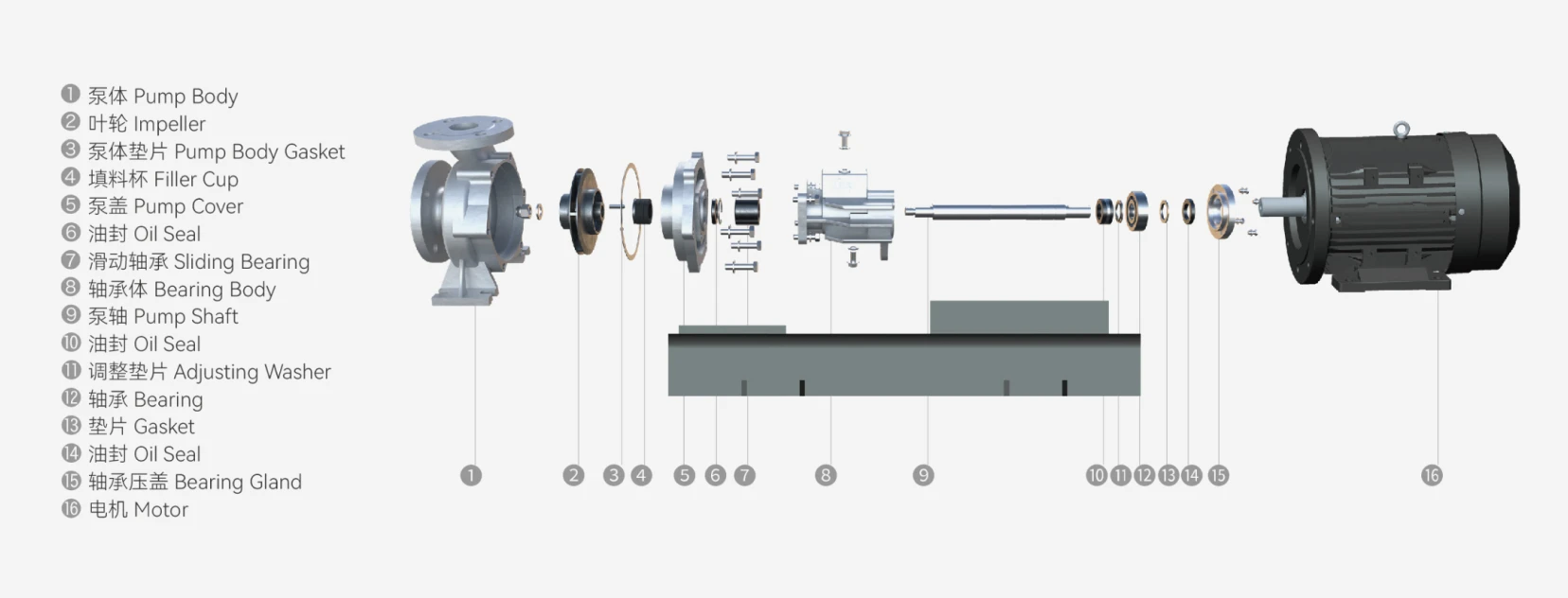
Cooling Mechanisms: Air vs. Water Cooling
To protect the bearings and the atmospheric side of the seal, heat must be dissipated.
Air-cooled thermal oil pumps dominate standard installations. They utilize an extended bearing housing outfitted with deep heat-dissipating fins. The ambient air draws the heat away from the bracket naturally. By the time the conductive heat reaches the mechanical seal chamber and ball bearings, the local temperature has dropped to a safe 90 °C to 110 °C, well within the operating limits of standard high-temp bearing greases.
Water-cooled pumps incorporate a cooling jacket around the seal chamber or bearing housing. This design is reserved for extreme temperatures (above 350 °C) or installations where ambient air circulation is too poor to rely on convective cooling. While highly effective, it adds infrastructure cost and requires continuous monitoring of the water supply.
Installation Best Practices for Hot Fluid Systems
A properly selected pump will still fail if installed incorrectly. Thermal expansion of piping is the leading cause of premature mechanical failure in hot oil systems. Steel pipes expand predictably when heated. If a rigid pipe run heats up and lengthens by 15 millimeters, that mechanical force is transferred directly into the pump flanges.
This pipe strain forces the pump casing out of alignment with the motor. Misalignment causes vibration, rapid bearing destruction, and shattered mechanical seal faces. Engineers must incorporate metallic expansion joints (compensators) or engineered pipe loops near the pump inlet and outlet to absorb this thermal growth. Furthermore, cold alignment done during installation must be re-checked and adjusted after the system reaches its final operating temperature (hot alignment).
Conclusion: Ensuring Heat Transfer Reliability
Sizing and selecting a high-temperature thermal oil pump requires executing precise calculations regarding fluid viscosity variations, flow resistance, and vapor pressure margins. The hardware chosen must possess the metallurgical strength to resist thermal shock and the proper engineering design—such as finned air-cooling barriers and metal bellows seals—to contain hazardous hot oil safely. Integrating the right pump guarantees that industrial heating processes run efficiently, safely, and without unplanned downtime. For technical support in sizing your next system, review our heavy-duty process solutions or contact engineering teams directly to match a high-temperature thermal oil pump to your exact duty cycle.