


In complex industrial processing, the transfer of aggressive, toxic, or highly valuable fluids presents a persistent engineering challenge. Traditional sealing mechanisms, while functional for clean water or benign fluids, inevitably degrade when exposed to harsh chemicals, abrasive particulates, or extreme thermal cycling. This degradation results in mechanical seal failure, fugitive emissions, and costly unplanned downtime. For modern facilities, the standard solution for critical fluid handling has transitioned toward zero-leakage technologies.
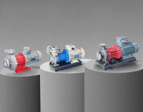
At the forefront of this shift is the industrial magnetic drive pump. By eliminating the dynamic mechanical seal, these systems provide a hermetically sealed environment that isolates the process fluid from the atmosphere. This technical article explores the mechanical principles, material engineering, sizing criteria, and operational best practices for specifying and maintaining these specialized fluid transfer systems.

1. How Sealless Centrifugal Pumps Work: The Principles of Magnetic Coupling
The fundamental architecture of sealless centrifugal pumps diverges significantly from traditional mechanically sealed configurations. In a conventional pump, the motor shaft extends directly through the pump casing to turn the impeller. This penetration point requires a mechanical seal or packing to prevent fluid from escaping—a design inherently susceptible to wear and eventual leakage.
A magnetic drive pump eliminates this penetration entirely. The operational torque from the electric motor is transmitted to the impeller across a static containment shell using a synchronous magnetic coupling. This system consists of three primary components:
- The Outer Magnetic Rotor (Drive Magnet): Connected directly to the motor shaft, this component rotates outside the containment shell. It is typically fitted with a series of permanent rare-earth magnets (such as Neodymium-Iron-Boron or Samarium-Cobalt) arranged in an alternating pole configuration.
- The Containment Shell (Rear Casing): A static, pressure-retaining barrier that completely seals the fluid within the pump end. It sits between the outer and inner magnetic rotors.
- The Inner Magnetic Rotor (Driven Magnet): Encapsulated within the process fluid and directly attached to the pump impeller. As the outer rotor spins, the magnetic flux passes through the containment shell, locking with the inner rotor and forcing the impeller to turn at a synchronous speed.
Because there is no physical connection between the motor shaft and the impeller, there is no dynamic seal. The only seals present are static O-rings or gaskets between the pump casing and the containment shell, effectively reducing the leak path to zero under normal operating conditions.

2. Core Advantages of Magnetically Driven Chemical Pumps Over Mechanically Sealed Alternatives
The transition from conventional seals to magnetically driven chemical pumps in process industries is driven by strict operational imperatives: environmental compliance, operator safety, and lifecycle reliability.
Absolute Zero Leakage and Safety
When handling lethal, volatile, or highly corrosive fluids (such as hydrofluoric acid, sodium hydroxide, or liquid chlorine), a seal failure is not merely a maintenance issue; it is a critical safety incident. Magnetic drive technology ensures complete fluid containment. This makes them indispensable in the chemical, petrochemical, and semiconductor industries where exposure to process media can result in severe personnel injury or catastrophic equipment damage.
Elimination of Seal Support Systems
Complex mechanical seals, particularly double mechanical seals used for hazardous fluids, require elaborate seal support systems (API plans). These systems require barrier fluids, heat exchangers, and continuous monitoring instrumentation. By utilizing sealless technology, engineers can eliminate this auxiliary equipment, simplifying the overall footprint, reducing installation costs, and removing secondary points of failure.
Improved Mean Time Between Failures (MTBF)
Mechanical seals are the leading cause of pump failure in the process industry. By removing the mechanical seal, the primary wear component is eliminated. While magnetic pumps rely on internal process-lubricated bearings (often made of silicon carbide), these bearings exhibit exceptionally long lifespans when properly applied and kept free of dry-running conditions. The result is a significantly higher MTBF compared to mechanically sealed counterparts.
Compliance with Environmental Regulations
Fugitive emissions from industrial equipment are heavily regulated. According to the , equipment leaks—including those from pump seals—are the largest source of volatile organic compound (VOC) emissions from petroleum refineries and chemical manufacturing facilities. Sealless pumps inherently comply with the strictest environmental regulations by eliminating the emission pathway.

3. Material Selection for Mag-Drive Process Pumps in Corrosive Environments
The reliability of mag-drive process pumps depends heavily on selecting the correct materials for the wetted components, internal bearings, and the containment shell. Because these pumps are often deployed in the most aggressive chemical environments, metallurgy and polymer science play critical roles in their construction.
Casing and Impeller Materials
For highly corrosive applications, metallic casings are often insufficient. In these scenarios, pumps are typically constructed with an outer armor of ductile iron or cast iron for structural integrity and pressure containment, lined with thick, injection-molded fluoroplastics. Materials such as PTFE (Polytetrafluoroethylene), PFA (Perfluoroalkoxy), and F46 (Fluorinated ethylene propylene) offer near-universal chemical resistance. For example, systems built to the HG/T2730 standard utilize one-time molding techniques to ensure a seamless, non-permeable protective layer against aggressive acids and alkalis. For clean water, solvents, or mildly corrosive applications, stamped or cast 304/316L stainless steel provides an excellent balance of strength and corrosion resistance.
Containment Shell Engineering
The containment shell is the most highly engineered component of the pump. It must be strong enough to withstand the maximum system pressure, thin enough to allow optimal magnetic flux transmission, and chemically inert to the process fluid.
- Metallic Shells (Hastelloy, Titanium, 316SS): Provide high pressure and temperature ratings but are subject to "eddy current losses." As the magnetic field rotates through the conductive metal, it generates electrical currents (eddy currents) that manifest as heat. This heat must be dissipated by the process fluid.
- Non-Metallic Shells (Carbon Fiber Reinforced PFA, PEEK, Ceramics): These materials do not conduct electricity; therefore, they do not generate eddy currents. This eliminates heat generation in the containment shell, making them ideal for temperature-sensitive fluids or highly volatile liquids near their vapor pressure.
Internal Bearings and Shafts
Because there is no external lubrication, the internal bearings must be lubricated by the process fluid itself. Sintered Silicon Carbide (SiC) is the industry standard due to its extreme hardness, near-zero wear rate, and universal chemical resistance. High-purity ceramics are also utilized in less abrasive applications.

4. Handling Extreme Temperatures with Zero-Leakage Chemical Circulation Pumps
Industrial processes frequently operate at extreme thermal boundaries, from cryogenic liquefied gases (-196°C) to high-temperature heat transfer fluids (+400°C). Deploying zero-leakage chemical circulation pumps in these environments requires specific engineering adaptations to manage thermal expansion, heat dissipation, and material stability.
High-Temperature Operations
When pumping thermal oils or high-temperature chemicals, the heat from the process fluid transfers through the pump casing toward the motor and magnetic coupling. Permanent magnets, particularly Neodymium, are sensitive to heat; if they exceed their Curie temperature, they will irreversibly lose their magnetic strength (demagnetization).
To combat this, extreme-temperature pumps utilize Samarium-Cobalt (SmCo) magnets, which possess a much higher thermal threshold. Additionally, specialized heat-dissipating structures are employed. For instance, extended cooling fins between the pump head and the motor adapter allow for natural convection cooling (air-cooled configurations), effectively reducing the temperature at the magnetic coupling without requiring complex external water-cooling jackets.
Low-Temperature and Cryogenic Operations
In low-temperature applications, such as liquid nitrogen or cold brine circulation, the primary challenge is material embrittlement and thermal contraction. Standard cast irons or certain plastics will shatter under cryogenic stress. Austenitic stainless steels are strictly required for structural components, and internal clearances between the impeller, casing, and bearings must be precisely machined to account for the differential thermal contraction rates of dissimilar materials.
For facilities operating complex thermal systems, exploring specialized designed explicitly for extreme temperature gradients is essential for maintaining process stability.

5. Common Failure Modes in Magnetic Coupled Fluid Transfer Systems and How to Prevent Them
While highly reliable, magnetic coupled fluid transfer systems are not indestructible. They have specific operational vulnerabilities that differ from mechanically sealed pumps. Understanding these failure modes is critical for system designers and plant operators.
Dry Running: The Critical Vulnerability
The internal silicon carbide bearings rely entirely on the process fluid for lubrication and cooling. If the pump is run without fluid (dry running), the friction between the bearing components generates immense heat within seconds. Because SiC is brittle, thermal shock combined with thermal expansion will cause the bearings to shatter, leading to a catastrophic internal crash where the inner magnetic rotor strikes the containment shell.
- Prevention: The installation of power monitors (which detect the drop in motor load associated with dry running) or optical/tuning-fork liquid level sensors in the suction line is strictly mandatory to shut down the motor instantly upon loss of fluid.
Decoupling (Magnetic Slippage)
Decoupling occurs when the torque required to turn the impeller exceeds the maximum transmittable torque of the magnetic coupling. When this happens, the outer magnet spins, but the inner magnet stops. The alternating magnetic poles crossing each other rapidly induce severe eddy currents, causing the internal temperature to spike violently.
- Prevention: Decoupling is typically caused by pumping a fluid with a specific gravity or viscosity much higher than the pump was sized for, or by a severe internal mechanical blockage. Accurate fluid specification during the sizing phase and installing proper suction strainers prevent this issue.
Cavitation and Flashing
If the Net Positive Suction Head Available (NPSHa) drops below the pump's required NPSHr, the fluid will vaporize inside the impeller eye. This causes vibration, loss of flow, and potential bearing damage. Furthermore, if a metallic containment shell is used, the localized heat from eddy currents can cause volatile fluids to flash into gas within the rear casing, depriving the rear bearings of lubrication.
- Prevention: Ensure proper system design with adequate suction head, and consider non-metallic containment shells when pumping fluids near their boiling points.

6. Sizing and Specifying Sealless Magnetic Pumps for Your Facility
Accurate engineering specification is non-negotiable when deploying sealless magnetic pumps. Unlike standard pumps, where a slightly oversized motor might mask an application error, a misapplied magnetic drive pump will fail predictably.
Calculating Flow and Head Requirements
The baseline for any pump selection is identifying the required flow rate (Capacity) and Total Dynamic Head (TDH). TDH must account for the static lift, pipeline friction losses, and the pressure drop across all valves, filters, and heat exchangers in the system.
Fluid Characteristics: Viscosity and Specific Gravity
Magnetic couplings are rated for a specific maximum torque.
- Specific Gravity (SG): The density of the fluid directly affects the horsepower required to move it. Pumping 98% sulfuric acid (SG 1.84) requires almost twice the torque as pumping water (SG 1.0). The magnetic coupling must be sized to handle this increased load to prevent decoupling.
- Viscosity: High-viscosity fluids create significant friction within the tight clearances of a magnetic pump. If the viscosity exceeds approximately 150-200 cSt, the performance drops drastically, and the torque requirement spikes. For high-viscosity applications, engineers should pivot away from centrifugals and specify positive displacement technology.
Understanding System Pressures
Engineers must differentiate between differential pressure (the head generated by the pump) and maximum allowable working pressure (MAWP). If a pump is drawing from a highly pressurized tank, the containment shell must be rated to withstand that static background pressure safely, regardless of the pump's operational state.
When building your procurement specifications, reviewing a broad range of industrial centrifugal pumps will help establish a baseline for your required hydraulic coverage before narrowing down to magnetic drive options.

7. Energy Efficiency and Lifecycle Costs of Magnetically Actuated Process Pumps
When evaluating the procurement of magnetically actuated process pumps, industrial buyers must look beyond the initial capital expenditure (CAPEX) and analyze the Total Cost of Ownership (TCO) and overall energy efficiency.
Technical Comparison: Magnetic Drive vs. Mechanical Seal
| Feature / Metric | Magnetic Drive Pump | Double Mechanical Seal Pump |
| Leakage Rate | Absolute Zero | Minimal to Moderate (depending on seal condition) |
| Seal Support System | Not Required | Required (API Plan 52, 53A, 54, etc.) |
| Initial CAPEX | High | Medium to High (when including support systems) |
| Maintenance Frequency | Low (Inspect bearings every 2-3 years) | High (Regular seal and barrier fluid replacement) |
| Tolerance to Dry Running | Extremely Low (Without specialized bearings) | Low to Moderate (Depending on seal flush) |
| Energy Efficiency (Metallic Shell) | Slightly lower due to eddy current losses | Standard motor efficiency |
| Energy Efficiency (Non-Metallic) | Equal to standard centrifugal | Standard motor efficiency |
Lifecycle Cost Analysis
While the upfront cost of a magnetic drive pump is generally higher than a standard mechanically sealed pump, the TCO heavily favors the sealless design in aggressive applications. The financial savings are realized through the elimination of barrier fluid consumption, the removal of cooling water utility costs for seal support plans, significantly reduced maintenance man-hours, and the avoidance of EPA fines or cleanup costs associated with fluid leaks.
Managing Efficiency Losses
It is mechanically true that magnetic drive pumps with metallic containment shells suffer an efficiency penalty of 5% to 15% due to eddy current losses. However, in continuous-duty applications, this can be mitigated by specifying non-metallic (e.g., carbon fiber composite) containment shells, which completely eliminate magnetic drag and restore the pump's hydraulic efficiency to parity with traditional mechanically sealed units.
8. Global Regulations Shaping the Future of Mag-Drive Industrial Pumping Systems
The industrial equipment landscape is not evolving purely based on mechanical innovation; it is being aggressively shaped by international regulatory frameworks. The adoption curve for mag-drive industrial pumping systems is accelerating due to stringent new directives targeting environmental protection and energy consumption.
The Push for PFAS Elimination
Per- and polyfluoroalkyl substances (PFAS), widely known as "forever chemicals," are facing severe regulatory restrictions globally. The impending bans on specific PFAS compounds mean that industrial facilities must be meticulous in how they handle, transfer, and contain these chemicals during the phase-out and transition periods. Any leakage of PFAS-containing fluids from mechanical seals is becoming a major legal and environmental liability. Sealless magnetic technology provides the closed-loop containment necessary to comply with zero-discharge mandates during chemical processing.
Ecodesign and Energy Directives
In the European Union, the Ecodesign for Sustainable Products Regulation (ESPR) and the existing Regulation (EU) 547/2012 for water pumps are driving manufacturers to optimize hydraulic efficiency. As industrial buyers look to reduce their carbon footprint, pump selection is increasingly dictated by the Minimum Efficiency Index (MEI). Magnetic drive pump manufacturers are responding by utilizing advanced computational fluid dynamics (CFD) to optimize impeller geometries and transition to permanent magnet synchronous motors (PMSM) to offset the energy losses associated with magnetic couplings.
Safety Standards in Chemical Handling
In regions governed by OSHA (Occupational Safety and Health Administration) or equivalent international safety bodies, the Process Safety Management (PSM) standards require facilities handling highly hazardous chemicals to implement rigorous mechanical integrity programs. Standardizing on sealless magnetic pumps simplifies PSM compliance by structurally removing the most common failure point (the mechanical seal) from the hazardous fluid loop.
Conclusion
The engineering logic behind specifying industrial magnetic drive pumps is clear: when the cost of a leak—measured in safety, environmental impact, or operational downtime—exceeds the capital cost of the equipment, sealless technology is the required solution. By understanding the intricate mechanics of magnetic coupling, making informed metallurgical choices, and strictly adhering to operational parameters regarding fluid levels and temperatures, process engineers can achieve decades of reliable, zero-leakage fluid transfer in the most demanding industrial environments.