


In the vast landscape of industrial fluid transfer, engineers frequently encounter a specific thermodynamic challenge: moving a relatively small volume of liquid against an exceptionally high system resistance. When the application demands low flow rates combined with high discharge pressures—such as in boiler feed systems, reverse osmosis filtration, or precise chemical dosing loops—standard kinetic pumping technologies quickly reach their mechanical and hydraulic limits. Attempting to force a standard oversized impeller to operate in a low-flow, high-head state results in massive inefficiency, severe shaft deflection, and rapid seal failure.
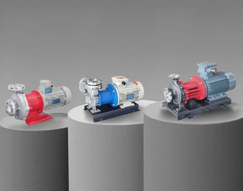
The precise engineering solution for this operational envelope is the industrial vortex pump. Often referred to interchangeably in the industry as a regenerative turbine pump or a peripheral pump, this specialized equipment leverages a unique method of energy transfer to build immense pressure within a highly compact footprint. This comprehensive guide details the fluid mechanics, system integration strategies, and operational parameters necessary to successfully deploy this technology in demanding industrial environments.
1. The Mechanics Behind Regenerative Turbine Pumps in Fluid Systems
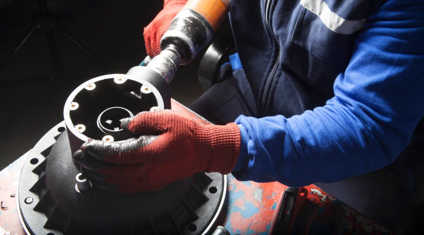
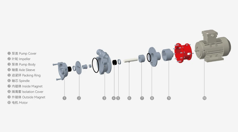
Understanding how a regenerative turbine pump operates requires visualizing a fluid path fundamentally different from a standard volute casing. The core component is the impeller, which features a solid disc with dozens of small, precision-machined vanes cut into its periphery on both sides. This impeller rotates within a tightly machined annular channel (the casing).
As fluid enters the suction port, it is directed into the root of the rotating impeller vanes. Centrifugal force immediately throws the fluid outward toward the casing wall. However, the internal geometry forces the fluid to bounce back off the casing wall and return into the root of the next rotating vane. This creates a continuous, spiral-like corkscrew path—a "regenerative" cycle. With every single rotation of the fluid within this annular channel, additional kinetic energy is imparted by the impeller. By the time the fluid reaches the discharge port, it has been accelerated and pressurized multiple times, allowing the pump to generate discharge heads up to ten times higher than a standard kinetic pump operating at the exact same motor speed and impeller diameter.
2. Comparing Industrial Vortex Pumping Equipment to Standard Centrifugals
To accurately specify equipment for a process loop, plant engineers must understand the distinct differences in performance curves between industrial vortex pumping equipment and traditional centrifugal units.
A standard centrifugal pump features a relatively flat head-to-flow curve. If system pressure increases slightly, flow rate drops significantly. Furthermore, its power consumption curve peaks at the maximum flow rate (the far right of the curve).
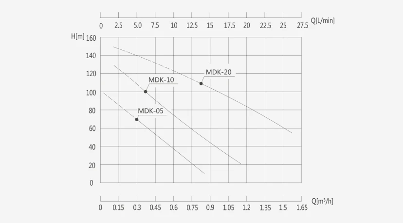
Conversely, a vortex pump exhibits an extremely steep, almost linear head-to-flow curve. A significant increase in system backpressure will result in only a marginal decrease in flow rate, making them exceptionally stable for pressure-variable systems. Crucially, the brake horsepower (BHP) curve of a vortex unit is the exact opposite of a standard centrifugal: power consumption peaks at the maximum pressure (shut-off head) and drops as flow increases.
| Mechanical & Hydraulic Metric | Standard Centrifugal Pump | Industrial Vortex Pump |
| Optimal Duty Point | High Flow, Low to Medium Head | Low Flow, Extremely High Head |
| Impeller Design | Open, Semi-Open, or Closed Vanes | Solid disc with peripheral vanes |
| Performance Curve | Flat to moderately steep | Very steep and highly stable |
| Power Consumption (BHP) | Peaks at maximum flow (open valve) | Peaks at zero flow (closed valve) |
| Clearance Tolerance | Moderate | Extremely tight (0.001 to 0.003 inches) |
| Vapor Handling | Poor (Prone to air-locking) | Excellent (Handles up to 20% entrained gas) |
3. High-Head Applications for Peripheral Pump Technology
Because of their unique hydraulic profile, peripheral pump technology is deployed in highly specific industrial sectors where space is constrained, but pressure requirements are severe.
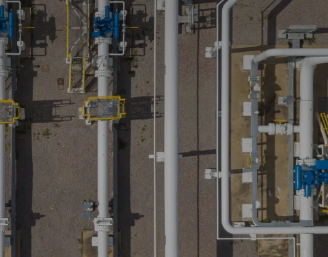
One of the most prominent applications is in industrial temperature control units (TCUs) and thermal management systems. Whether circulating highly refined heat transfer fluids at 300°C or moving cryogenic coolants at -100°C, the tight footprint and high-pressure capability allow these units to overcome the immense friction losses found in the long, serpentine coils of industrial heat exchangers. Additionally, they are the industry standard for high-pressure spraying applications, localized wash-down systems, and feeding filter presses where the hydraulic resistance continuously increases as the filter cake builds. By utilizing a pump that delivers consistent flow against rising backpressure, process engineers can ensure uniform filtration and precise thermal regulation.
4. Managing Entrained Gas with Liquid Ring Vortex Pumping Systems
One of the most catastrophic conditions for a standard fluid transfer system is the introduction of air or vapor into the suction line. When a traditional impeller encounters a vapor pocket, the fluid's specific gravity drops precipitously. The pump loses its ability to generate differential pressure, resulting in an "air-lock" condition where the fluid completely stops moving while the motor continues to spin, rapidly burning out the mechanical seals.
Liquid ring vortex pumping systems completely circumvent this vulnerability. The regenerative action within the annular channel creates a highly turbulent mixture of liquid and gas. The tight clearances prevent the gas from collecting at the impeller eye. Instead, the pump effectively compresses the gas and forces it through the discharge port along with the liquid. Many engineered peripheral units can easily handle fluids containing up to 20% entrained non-condensable gases. This makes them invaluable for pumping volatile solvents near their boiling points, extracting condensate from steam systems, or emptying tanks where drawing in air at the end of the batch is unavoidable.
5. Material Engineering for Corrosive Environments in Regenerative Pumps
The hydraulic efficiency of regenerative pumps is entirely dependent on maintaining the microscopic clearances between the rotating impeller and the static casing. If these clearances expand due to chemical corrosion or abrasive wear, fluid will "slip" backward inside the casing, and the pump will completely lose its ability to generate high pressure.
Therefore, material selection in aggressive environments is uncompromising. For basic clean water or light oils, standard cast iron is acceptable. However, for process industries handling deionized water, aggressive chemical solvents, or acidic compounds, the wetted components must be precision-machined from 304 or 316L stainless steel. Stainless steel prevents oxidative degradation and maintains the tight dimensional tolerances required for regenerative fluid dynamics over years of continuous operation. In environments with heavy particulate matter, engineers must install fine-mesh suction strainers, as the tight internal clearances cannot pass solids without severe mechanical scoring.
6. Magnetic Drive Configurations for Zero-Leakage Vortex Transfer Pumps
In modern chemical synthesis and high-temperature manufacturing, environmental regulations and personnel safety standards mandate zero-leakage fluid handling. Traditional mechanical seals, regardless of their flush plans, will eventually wear and allow fugitive emissions to escape.
To meet these strict containment requirements, manufacturers integrate sealless technology with high-head hydraulics, creating magnetic drive vortex transfer pumps. In this architecture, a static containment shell (made of stainless steel or advanced alloys) isolates the fluid. An external magnetic rotor driven by the motor magnetically couples with an internal rotor attached to the peripheral impeller. This design eliminates the dynamic shaft seal entirely. When dealing with lethal chemicals, explosive solvents, or high-temperature thermal oils where a leak could result in an instant fire, the sealless peripheral unit offers the perfect combination of absolute fluid containment and high-pressure delivery.
7. Calculating System Curve Matches for High-Pressure Vortex Fluid Pumps
Specifying high-pressure vortex fluid pumps requires a different engineering approach than sizing standard flow equipment. Because the brake horsepower increases as the discharge pressure increases, the greatest risk to the motor is a restricted or closed discharge line.
If a downstream valve is accidentally closed while a vortex unit is running, the pressure will spike instantly to the pump's shut-off head, potentially rupturing piping, blowing gaskets, or overloading the electrical drive. Therefore, system design must legally and mechanically incorporate an external Pressure Relief Valve (PRV) installed as close to the pump discharge as possible, routing back to the supply tank. When calculating the Net Positive Suction Head available (NPSHa), engineers must also account for the fluid's specific gravity carefully. While these units are excellent at building head, pumping heavy, viscous fluids will drastically increase internal friction, requiring a significant up-sizing of the motor to prevent decoupling or thermal tripping.
8. Maintenance Best Practices for Industrial Peripheral Turbine Pumps
To maximize the Mean Time Between Failures (MTBF) and preserve hydraulic efficiency, maintenance teams must adhere to strict operational protocols when managing industrial peripheral turbine pumps.
The primary maintenance focus must be on fluid cleanliness. Because the operational clearances between the impeller and the casing are often less than the thickness of a human hair, even microscopic pipe scale or welding slag can instantly seize the impeller, snapping the motor shaft. Commissioning a new system requires extensive flushing of the pipework before the unit is permanently installed.
Furthermore, vibration monitoring is critical. While these units operate with very low vibration under normal conditions, any bearing wear will cause the shaft to deflect. Given the tight internal tolerances, even a fraction of a millimeter of shaft deflection will cause the metallic impeller to rub against the metallic casing. This friction generates massive localized heat, leading to rapid catastrophic failure. Regular laser alignment of the motor shaft and strict adherence to the lubrication schedules published by the manufacturer will ensure the equipment operates continuously within its engineered parameters.