


A lithium battery cell plant runs on fluids. Slurry gets mixed and coated, solvent gets dried off and recovered, electrolyte gets dosed into finished cells, and chilled and hot loops hold every step at temperature. Most of those fluids are corrosive, flammable, toxic, or so moisture-sensitive that a trace of water spoils the cell. The pumps that move them are not a side issue. Pick the wrong one and you get seal leaks in a flammable-solvent area, water ingress that hydrolyzes your electrolyte, or a contaminated coating that scraps a roll of electrode. This guide covers the pump duties in lithium battery manufacturing where the fluid, not the flow, decides the pump.
We have built sealless magnetic-drive and magnetic gear pumps for new-energy customers for years, including electrolyte and solvent handling and coating-line circulation. One example: a German lithium battery separator-coating line runs our MDH vortex magnetic pumps with custom motors. Below we walk the cell-manufacturing process station by station — electrolyte, NMP solvent and its recovery loop, binder and additive dosing, and coating-line thermal control — with the material, leak-tightness, and dosing requirements that set battery-chemistry pump duty apart from ordinary transfer. Where a duty falls outside sealless-pump territory, and abrasive electrode slurry is the main one, we say so plainly.
1. The Pump Duties in a Lithium Battery Cell Plant
Leave aside plain utility water, which is conventional centrifugal work. The fluid-handling side of a cell plant breaks down into these pump duties, each with a different medium and accuracy requirement:
● Slurry transfer and coater feed — moving cathode (NMP-based) and anode (water-based) slurry from the mixers to the coating die. High-solids, abrasive, and shear-sensitive.
● Binder and additive dosing — metering PVDF binder solution and conductive-additive dispersions into the mix at a controlled ratio.
● NMP solvent transfer and recovery — feeding the coating process and pumping recovered solvent through the condensation and distillation loop back to mixing.
● Electrolyte transfer and dosing — moving LiPF₆ electrolyte from drums and IBCs to day tanks and feeding the filling machines, leak-free and moisture-tight.
● Coating-line and process thermal control — circulating chilled glycol to jacketed mixers and dry rooms, and hot fluid or thermal oil to heated rolls and drying zones.
● Formation and utility cooling — clean-fluid circulation for formation, aging, and general process cooling.
Four requirements cut across the chemical duties: material compatibility with HF-forming electrolyte and aggressive solvents, absolute leak-tightness in flammable-solvent areas, exclusion of atmospheric moisture from the electrolyte path, and dosing accuracy that holds a coating or fill setpoint. The abrasive electrode slurry is a separate problem, solved with progressive-cavity or peristaltic pumps. The electrolyte, solvent, dosing, and thermal-control duties are where sealless magnetic-drive and magnetic gear pumps are the right tool, and that is what this guide focuses on.
2. Electrolyte: Why It Needs a Moisture-Tight, Sealless Pump
Lithium-ion electrolyte is a lithium salt — almost always LiPF₆ — dissolved in a blend of organic carbonate solvents such as EC, DMC, and EMC. It is corrosive, flammable, and extremely moisture-sensitive. LiPF₆ reacts with even trace water through a hydrolysis chain that ends in hydrofluoric acid (HF), which attacks metals, glass, and most pump materials and degrades the cell chemistry at the same time. So an electrolyte pump has to do two jobs at once: keep the electrolyte in, and keep humid air out.
That rules out a packed or mechanically sealed pump. A seal is both a leak path for flammable solvent vapor and an ingress path for moisture. A sealless magnetic-drive pump closes both: torque crosses a static containment shell through a magnetic coupling, so there is no dynamic seal at all. Wetted parts have to be non-metallic or fluoropolymer-lined — PTFE, PFA, or ETFE — running on silicon-carbide bearings, because any metal wetted part corrodes once HF forms. One detail catches plants out: the elastomers. Carbonate solvents swell standard FKM (Viton) O-rings until they lose their seal, so FFKM (perfluoroelastomer) is the standard specification for electrolyte service.
The solvent blend is flammable, so electrolyte and solvent pump areas are usually classified ATEX or IECEx Zone 1 or Zone 2. The motor needs an Ex rating matched to the area classification — confirm it against the plant's hazardous-area drawing before you buy. Our AMC-F PTFE-lined magnetic drive pump is the fluoropolymer-lined, sealless build this duty calls for, and it pairs with our Leak-Proof Pump Solutions and Corrosion-Resistant Pump Solutions for the wider corrosive-handling picture.
3. Electrolyte Transfer, Dosing, and Filling
There are three distinct electrolyte pump duties, and they do not all use the same pump. Bulk transfer moves electrolyte from delivery drums or IBCs to day tanks and buffer vessels — a continuous, leak-free, moisture-tight duty. Metered feed delivers electrolyte to the filling machine's buffer at a controlled rate. The final dose into each cell — microliters for a coin cell, grams for a pouch or prismatic cell, usually pulled in under vacuum — is handled by the filling machine's own precision metering head, typically a ceramic plunger or peristaltic unit built for ±0.5–1% single-shot accuracy. That micro-dose head is part of the filling equipment. The pump you specify separately is the one that transfers and feeds electrolyte to it.
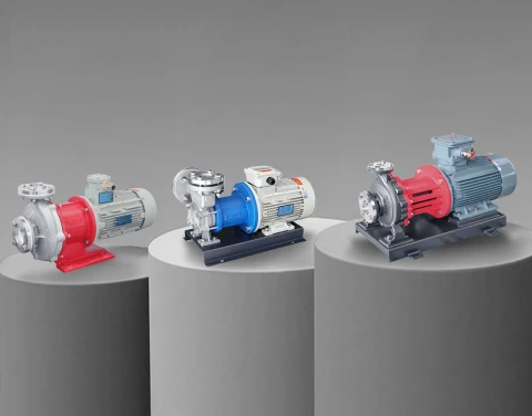
For drum or IBC-to-tank transfer and tank-to-machine feed, a sealless magnetic gear pump gives smooth, repeatable, pulsation-free volumetric flow with no seal to leak or admit moisture. The MDC-M micro magnetic gear pump suits small-volume electrolyte and additive dosing; the MDC-K magnetic gear pump and the MDC-X medium-to-large magnetic gear pump handle higher transfer rates. For larger leak-free transfer straight from bulk storage, the AMC-F PTFE-lined magnetic drive pump keeps the whole path inert and contained from drum to day tank.
4. NMP Solvent: Handling and Recovery Pumps
NMP (N-methyl-2-pyrrolidone) is the solvent that dissolves the PVDF binder in cathode slurry. It is expensive, a regulated VOC, and a reproductive toxin, so a modern coating line does two things with it: handles it leak-free, and recovers it. NMP boils at about 203°C and is fully miscible with water, and both facts shape the recovery process and the pump choice.
During electrode drying, the coating-oven exhaust carries NMP vapor. A cold-condensation system recovers roughly 90–95% of it as liquid; the saturated tail gas passes through a zeolite or activated-carbon rotor concentrator and often a regenerative thermal oxidizer for final VOC compliance. The recovered NMP is then distilled, using its high boiling point and water miscibility, and returned to slurry mixing. That loop carries several pump duties: transferring recovered condensate, feeding and refluxing the distillation column, and returning purified NMP to the mix room, some of it hot.
Sealless pumps suit all of it. For NMP transfer and recovery service, the AMC-L chemical process magnetic drive pump and AMC-F PTFE-lined magnetic drive pump give leak-free handling of the solvent, and a MDC-K magnetic gear pump gives metered, pulseless delivery where a fixed feed rate is needed. Hot distillation duty is within reach of the magnetic-drive build with the correct temperature rating. There is a regulatory angle here too: fluoropolymer and PFAS rules are tightening, and our note on PFAS regulations and chemical pump requirements covers what that means for lined-pump specification.
5. Slurry Binder and Additive Dosing
Electrode slurry itself is the one duty in the cell plant that sealless gear and vortex pumps are not built for. Cathode slurry (active material plus PVDF binder in NMP) and anode slurry (graphite with a water-based CMC and SBR binder) are high-solids, abrasive, shear-sensitive, and strongly shear-thinning, with viscosity that swings by orders of magnitude across the line. Bulk slurry transfer from mixer to coater is standard progressive-cavity (mono) or peristaltic territory, and the slot-die coater needs a pulseless feed. That hardware usually ships with the coating line.
Magnetic gear pumps are the right tool for the lower-abrasion metered duties around the mixer — dosing PVDF binder solution, conductive-additive dispersions, and other low-to-moderate viscosity feeds at a controlled ratio, pulsation-free and leak-free. The MDC-M micro magnetic gear pump handles small-volume precise dosing; the MDC-K magnetic gear pump steps the flow up. For abrasive high-solids slurry, a positive-displacement pump built for solids is the correct choice, and our positive displacement pump working principle and selection guide explains the trade-offs. The full Positive Displacement Pump Series covers the gear and vane range.
6. Coating-Line and Process Thermal Control
A cell line runs hot and cold loops in parallel, and each needs a clean, leak-free circulation pump. High-shear slurry mixing generates heat, so cathode and anode mixers are jacketed and held at temperature with chilled water or glycol. Battery dry rooms, kept at an extremely low dew point, run desiccant dehumidifiers backed by chiller and glycol loops. On the hot side, where a line heats its calender rolls or supplies hot fluid to drying zones, it circulates hot water or thermal oil.
Sealless vortex magnetic pumps cover the clean hot-and-cold circulation duties without a seal to leak coolant or admit air. The MDW stainless steel vortex magnetic pump and MDH stainless steel vortex magnetic drive pump handle chilled-glycol and hot-fluid circulation — the MDH-class pump is what runs on the German separator-coating line referenced earlier. Where the duty is genuine thermal oil at high temperature, the WRY-H high-temperature thermal oil pump is built for it. For the wider temperature-control range, see our high-temperature pump solutions and the EV battery testing pump solutions used on the cell-testing side.
7. Material Compatibility for Battery-Chemistry Pumps
Material selection is the decision that separates a pump that lasts from one that fails in weeks. This table summarizes the wetted-material and elastomer choices for the main battery-manufacturing fluids.
| Fluid | Key hazard | Wetted material | O-ring | Pump type |
| LiPF₆ electrolyte (carbonate solvents) | Corrosive (HF), flammable, moisture-sensitive | PTFE / PFA / ETFE lined, SiC bearings | FFKM | Sealless magnetic drive / magnetic gear |
| NMP solvent | Toxic VOC, hot in recovery | PTFE / PFA lined, or 316L when cool and dry | FFKM / FKM by temp | Magnetic drive / magnetic gear |
| PVDF binder / additive | Moderate, shear-sensitive | 316L or lined | FKM / FFKM | Magnetic gear (dosing) |
| Electrode slurry | High-solids, abrasive | Abrasion-resistant wetted parts | — | Progressive-cavity / peristaltic |
| Chilled glycol / water | Clean utility | 316L | EPDM / FKM | Vortex magnetic drive |
| Thermal oil (heated rolls / zones) | High temperature | Cast iron / steel, high-temp parts | High-temp | Thermal oil pump |
316L stainless steel is fine for clean utility water, glycol, and dry, cool NMP, but it is not a wetted material for electrolyte once any HF can form. That path has to be fluoropolymer-lined or non-metallic, full stop.
8. A Pump Selection Matrix for Lithium Battery Manufacturing
Mapped to the cell-plant stations, the pump choice comes out like this:
| Station | Fluid | Key requirement | Recommended pump |
| Bulk electrolyte transfer (drum/IBC to tank) | LiPF₆ electrolyte | Inert, sealless, moisture-tight | AMC-F PTFE-lined magnetic drive |
| Electrolyte feed / dosing to filler | LiPF₆ electrolyte | Pulseless, accurate, leak-free | MDC-M / MDC-K magnetic gear |
| Final cell fill | Electrolyte | Micro-dose, vacuum, ±0.5–1% | Filling-machine ceramic plunger / peristaltic (line OEM) |
| NMP transfer & recovery | NMP solvent | Leak-free, hot-capable | AMC-L / AMC-F magnetic drive |
| NMP metered feed | NMP solvent | Fixed-rate, pulseless | MDC-K magnetic gear |
| Binder / additive dosing | PVDF / additive | Accurate low-flow, low-shear | MDC-M / MDC-K magnetic gear |
| Electrode slurry to coater | Cathode / anode slurry | High-solids, abrasive, pulseless | Progressive-cavity / peristaltic (line OEM) |
| Mixer jacket / dry-room cooling | Chilled glycol / water | Clean, leak-free circulation | MDW vortex magnetic |
| Heated roll / drying-zone loop | Hot fluid / thermal oil | High-temperature circulation | MDH vortex magnetic / WRY-H thermal oil |
| Formation & utility cooling | Clean coolant / water | Continuous circulation | MDW / centrifugal magnetic drive |
9. Why Sealless Magnetic-Drive and Gear Pumps Fit Battery Manufacturing
The thread running through every chemical duty above is the seal, or the absence of one. Battery manufacturing is close to a textbook case for sealless pumps, because it stacks up every reason to delete the mechanical seal:
● Zero leakage of flammable solvent — no dynamic seal means no leak path in a Zone 1 or Zone 2 area.
● Moisture exclusion — the same containment shell that keeps electrolyte in keeps humid air out, protecting LiPF₆ from hydrolysis.
● No seal flush, no contamination — a sealless pump needs no barrier or flush fluid that could dilute or pollute a precise electrolyte or solvent.
● Dosing accuracy — magnetic gear pumps give repeatable, pulseless volumetric flow for binder, additive, and electrolyte metering.
● Long service life in clean duty — no seal to wear means fewer interventions in cleanroom and dry-room areas where access is restricted.
For a lithium battery line, sealless magnetic-drive pumps handle the corrosive and flammable transfer duties, magnetic gear pumps handle the metered dosing, and vortex magnetic pumps handle the hot-and-cold circulation. That is one sealless platform across the chemical, dosing, and thermal stations of the plant.
10. Aulank Lithium Battery Pump Portfolio
We supply sealless pumps into new-energy and battery manufacturing, matched to each station:
● AMC-F PTFE-lined magnetic drive pump — fluoropolymer-lined, sealless transfer of electrolyte and NMP solvent.
● AMC-L chemical process magnetic drive pump — chemical-process magnetic drive for solvent and corrosive transfer.
● MDC-M micro magnetic gear pump / MDC-K magnetic gear pump / MDC-X medium-to-large magnetic gear pump — pulseless metered dosing and transfer for electrolyte, binder, and additives, from micro-flow to medium-large flow.
● MDW stainless steel vortex magnetic pump / MDH stainless steel vortex magnetic drive pump — clean hot-and-cold circulation for mixer cooling, dry-room glycol, and heated-fluid loops.
● WRY-H high-temperature thermal oil pump — thermal-oil circulation for heated rolls and drying zones.
Every pump is built and tested to a documented quality process — ISO 9001, TÜV CE on the magnetic-drive vortex pumps, individual parameter test records, and 50+ patents on the synchronous permanent-magnet drive and shielded vortex hydraulics. Custom motors, including special voltage and frequency and the Ex ratings a battery line needs, are configured to the application. We have supplied battery and new-energy customers across China, Germany, and Asia. Send your fluid, concentration, flow, accuracy, and area-classification requirements and we will return a recommended portfolio with material specifications and quotes within two business days.
Browse the Chemical Pump Series, Positive Displacement Pump Series, and Vortex Pump Series, or read our magnetic drive pump selection guide and magnetic gear pump vs magnetic vortex pump comparison.
Get a Custom Lithium Battery Pump Configuration
Whether you run a gigafactory cell line, build coating and electrolyte-filling systems as an OEM, or operate a pilot and R&D line, our engineering team can match the right sealless magnetic-drive, magnetic gear, or vortex magnetic pump to each fluid-handling station in your plant.
Talk to our team: Contact Aulank | WhatsApp: +86 13773157367 | Email: info@aulankpump.com
Browse the relevant product and solution pages: