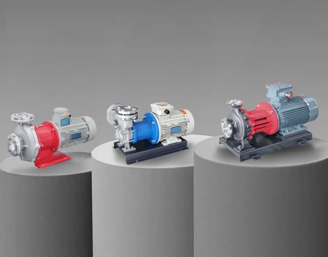


Magnetic drive pumps have become the standard solution for transferring hazardous, corrosive, and high-value fluids in industrial applications. By eliminating mechanical shaft seals, these sealless pumps achieve zero-leakage performance that conventional pump designs cannot match. However, within the magnetic drive pump category, two distinct technologies serve different application requirements: magnetic gear pumps and magnetic vortex pumps.
This technical comparison examines the operating principles, performance characteristics, and application suitability of both pump types. Engineers and procurement specialists will find the information needed to select the correct magnetic pump technology for specific fluid handling requirements.

Working Principles: How Each Magnetic Pump Type Operates
Understanding the fundamental operating mechanisms of magnetic gear pumps and magnetic vortex pumps reveals why each technology excels in different applications. Both utilize magnetic coupling to transmit torque from an external motor to internal rotating components, but the fluid displacement methods differ significantly.
Magnetic Gear Pump Operating Mechanism
A magnetic gear pump is a positive displacement pump that moves fluid through the meshing action of precision-machined gears. The pump contains two primary components: an external magnetic assembly connected to the motor shaft and an internal magnetic assembly connected to the driving gear.
When the motor rotates the external magnets, magnetic attraction causes the internal magnets to rotate synchronously. The internal magnets connect directly to the drive gear, which meshes with an idler gear inside the pump chamber. As both gears rotate, fluid enters the inlet port and fills the spaces between the gear teeth and the pump housing. The rotating gears carry this fluid around the periphery of the pump chamber and discharge it through the outlet port.
The gear meshing action creates a positive seal between inlet and outlet, meaning the pump displaces a fixed volume of fluid with each revolution regardless of discharge pressure. This characteristic makes magnetic gear pumps true positive displacement devices with predictable, repeatable flow rates.
External gear designs use two identical spur or helical gears rotating in opposite directions. Internal gear designs position one gear inside another with an eccentric arrangement. Both configurations achieve the same positive displacement principle but offer different advantages for specific viscosity ranges and flow requirements.
Magnetic Vortex Pump Operating Mechanism
A magnetic vortex pump operates on a different principle entirely. Also called a regenerative turbine pump or peripheral pump, this design generates head through repeated energy transfer between the impeller and the fluid.
The vortex pump impeller contains numerous small blades arranged around its periphery. As the impeller rotates, fluid enters the pump and contacts the blade tips. Each blade imparts kinetic energy to the fluid, accelerating it outward. The pump casing contains an annular channel that guides the fluid back toward the impeller, where it receives additional energy from subsequent blade passes.
This regenerative action means the fluid passes through the impeller multiple times during a single transit through the pump. Each pass adds energy, building discharge pressure progressively. The result is a pump capable of generating high heads relative to its impeller diameter and rotational speed.
The magnetic drive system in a vortex pump functions identically to other magnetic pump types. External drive magnets couple through a containment shell to internal driven magnets attached to the impeller shaft. The containment shell provides complete fluid isolation, eliminating any potential leak path.
Unlike positive displacement pumps, magnetic vortex pumps are kinetic devices. Their flow rate varies with discharge pressure according to a characteristic pump curve. At higher pressures, flow decreases; at lower pressures, flow increases.
Performance Characteristics and Operating Parameters
The different operating principles of mag drive gear pumps and magnetic vortex pumps produce distinct performance characteristics that determine application suitability.
Flow Rate and Pressure Capabilities
Magnetic Gear Pumps:
- Flow rates typically range from 0.1 mL/min to 200 L/min depending on pump size
- Discharge pressures can reach 25 bar (363 psi) or higher in heavy-duty designs
- Flow rate remains essentially constant regardless of pressure changes
- Low pulsation output suits precision metering applications
- Displacement per revolution is fixed and repeatable
Magnetic Vortex Pumps:
- Flow rates typically range from 5 L/min to 500 L/min
- Generate high heads relative to size (up to 250 meters in some designs)
- Head capability is 2-4 times higher than centrifugal pumps of similar size
- Flow rate varies inversely with discharge pressure
- Best efficiency occurs at specific head-flow combinations
Viscosity Handling Capabilities
Fluid viscosity significantly impacts pump selection between these two technologies.
Magnetic gear pumps excel with viscous fluids. The positive displacement action maintains efficiency even as viscosity increases. Many gear pump designs handle fluids from 1 cP (water-like) to 100,000 cP or higher. Higher viscosity actually improves volumetric efficiency by reducing internal slip between gears and housing.
Magnetic vortex pumps require low-viscosity fluids for efficient operation. The regenerative energy transfer mechanism depends on fluid flowing freely through the impeller channels. Viscosity above 5-10 cP significantly reduces pump head and efficiency. These pumps work best with water, light solvents, and similar thin liquids.

Temperature Range Comparison
Both magnetic pump types can be engineered for extreme temperature service, but standard configurations differ.
| Parameter | Magnetic Gear Pump | Magnetic Vortex Pump |
|---|---|---|
| Standard temperature range | -20°C to +200°C | -40°C to +200°C |
| Extended high temperature | Up to +350°C with special materials | Up to +400°C with special designs |
| Cryogenic capability | Limited (special designs required) | Down to -196°C available |
| Thermal cycling tolerance | Good | Excellent |
Magnetic vortex pumps often demonstrate superior performance in applications requiring wide temperature swings. The simpler internal geometry with fewer close-tolerance fits accommodates thermal expansion better than gear pumps with their precision gear meshes.
Structural Design and Component Differences
The mechanical construction of these two pump types reflects their different operating principles and creates distinct maintenance and reliability characteristics.
Internal Components and Materials
Magnetic Gear Pump Construction:
- Precision-machined gear sets (external or internal configuration)
- Close-tolerance fits between gears and housing (typically 0.025-0.075 mm)
- Bearing surfaces support gear shafts at both ends
- Common gear materials: PEEK, ceramic, stainless steel, Hastelloy
- Pump body materials: 316 stainless steel, Hastelloy, titanium
- Magnetic assembly typically uses rare-earth magnets (NdFeB or SmCo)

Magnetic Vortex Pump Construction:
- Multi-blade peripheral impeller
- Annular flow channel in pump casing
- Single shaft support (often cantilevered design)
- Common impeller materials: 316 stainless steel, Hastelloy, titanium
- Pump body materials: stainless steel, special alloys
- Isolation shell separates wet end from magnetic coupling

Size and Installation Considerations
Magnetic vortex pumps typically offer more compact packaging for a given head capability. Their ability to generate high pressure with small impeller diameters results in space-efficient designs. This makes them suitable for installations with limited footprint, such as equipment OEM integration.
Magnetic gear pumps require space proportional to their flow capacity. Larger flow requirements demand larger gear sets and pump bodies. However, for precision low-flow applications, micro gear pumps achieve extremely compact dimensions.
Both pump types install in similar configurations: horizontal mounting is standard, with vertical mounting available for specific models. Inlet and outlet connections follow standard pipe thread or flange specifications depending on pump size.
Application Suitability: Matching Pump Type to Process Requirements
The performance differences between magnetic gear pumps and magnetic vortex pumps make each technology optimal for specific application categories.
Ideal Applications for Magnetic Gear Pumps
Precision Metering and Dosing:
Chemical dosing systems require accurate, repeatable fluid delivery. The positive displacement action of gear pumps provides volumetric accuracy within ±0.5% regardless of viscosity changes or pressure variations. Pharmaceutical manufacturing, water treatment chemical feed, and adhesive dispensing benefit from this precision.
High-Viscosity Fluid Transfer:
Resins, polymers, oils, and other thick fluids flow efficiently through gear pumps. Applications include:
- Hot melt adhesive systems
- Polymer processing and extrusion
- Lubricating oil circulation
- Paint and coating transfer
- Silicone and sealant dispensing
Low-Flow, Moderate-Pressure Service:
When flow requirements are small but delivery pressure must overcome system resistance, gear pumps provide the necessary characteristics. Laboratory equipment, analytical instruments, and small-scale process systems often specify magnetic gear pumps.
Pulsation-Sensitive Processes:
The continuous meshing action of gear teeth produces nearly pulsation-free flow. Processes requiring smooth, steady flow without pressure spikes benefit from gear pump characteristics. Coating applications, spray systems, and sensitive instrumentation fall into this category.

Ideal Applications for Magnetic Vortex Pumps
High-Head, Low-Flow Circulation:
Temperature control systems, cooling loops, and circulation circuits often require high pressure capability with moderate flow rates. Magnetic vortex pumps generate heads of 50-250 meters while maintaining compact dimensions. Typical applications include:
- Mold temperature controllers
- Semiconductor process cooling (TCU systems)
- Die casting thermal management
- Laser cooling systems
- Welding equipment coolant circulation
Clean, Low-Viscosity Fluid Service:
Water, ethylene glycol, thermal oils (at operating temperature), refrigerants, and light solvents match vortex pump characteristics. The technology handles these fluids efficiently when cleanliness requirements prevent the use of conventional sealed pumps.
Gas-Liquid Mixture Handling:
Vortex pumps tolerate entrained gas better than most other pump types. The regenerative action continues functioning even with significant vapor content. This makes them suitable for applications where cavitation or vapor entrainment may occur.
Extreme Temperature Applications:
Cryogenic processes down to -196°C and high-temperature service up to +400°C fall within magnetic vortex pump capabilities. Semiconductor manufacturing, pharmaceutical freeze-drying, and chemical process heating/cooling systems utilize this temperature range.

Comparing Efficiency and Energy Consumption
Energy efficiency differs significantly between these pump technologies, though direct comparison requires context about operating conditions.
Magnetic Gear Pump Efficiency
Gear pump efficiency varies with viscosity, speed, and pressure. Peak mechanical efficiency typically reaches 70-85% under optimal conditions. Efficiency improves as viscosity increases because internal leakage (slip) decreases.
At very low viscosities, gear pump efficiency drops because fluid slips past the gear teeth without being displaced. This makes gear pumps less suitable for water-like fluids compared to vortex designs.
Power consumption follows the relationship:
Power = (Flow × Pressure) / Efficiency
The positive displacement characteristic means power consumption increases linearly with pressure at constant flow.
Magnetic Vortex Pump Efficiency
Vortex pump efficiency is inherently lower than centrifugal pumps due to the regenerative operating principle. Typical peak efficiency ranges from 35-50%. However, this comparison overlooks the vortex pump's ability to generate much higher head than a centrifugal pump of similar size.
When evaluated on a head-per-stage basis, vortex pumps often prove more practical than multi-stage centrifugal alternatives. A single vortex pump replacing a three-stage centrifugal pump may consume similar total power while offering simpler construction and lower maintenance.
Efficiency remains relatively stable across the operating range, making vortex pumps suitable for variable-duty applications where flow requirements change.

Maintenance Requirements and Service Life Expectations
Maintenance characteristics directly impact total cost of ownership and operational reliability for both pump types.
Magnetic Gear Pump Maintenance
Wear Components:
- Gear teeth experience gradual wear, especially with abrasive fluids
- Bearings require replacement based on operating hours and conditions
- Close tolerances mean wear eventually increases internal slip
Service Intervals:
- Typical service life: 5,000-20,000 hours depending on application
- Bearing inspection recommended every 2,000-4,000 hours
- Gear replacement when flow accuracy degrades beyond acceptable limits
Maintenance Considerations:
- Precision components require careful handling during service
- Gear sets should be replaced as matched pairs
- Cleanliness during assembly is critical
- Proper startup procedures prevent dry-running damage
Magnetic Vortex Pump Maintenance
Wear Components:
- Impeller blade tips experience gradual erosion
- Bearing surfaces (often ceramic or carbon) wear over time
- Containment shell remains maintenance-free under normal operation
Service Intervals:
- Typical service life: 10,000-50,000+ hours in clean fluid service
- Simpler construction generally means longer service intervals
- Bearing inspection at manufacturer-recommended intervals
Maintenance Considerations:
- Fewer precision fits simplify reassembly
- Impeller balance should be verified after service
- Magnetic coupling alignment must be maintained
- Running dry for extended periods damages bearings

Selection Criteria: Choosing Between Magnetic Gear and Vortex Pumps
A systematic evaluation of process requirements guides proper pump selection. Consider these factors when choosing between magnetic gear pumps and magnetic vortex pumps:
Primary Selection Factors
1. Fluid Viscosity
- Below 10 cP: Either type may work; vortex often preferred for efficiency
- 10-1,000 cP: Gear pump recommended
- Above 1,000 cP: Gear pump required
2. Flow Accuracy Requirements
- Precision metering (±1% or better): Gear pump
- General circulation (±5-10%): Either type
- Variable flow operation: Vortex pump adapts well
3. Head/Pressure Requirements
- High head, low flow: Vortex pump excels
- Moderate head, any flow: Either type
- High pressure against closed discharge: Gear pump (with relief valve)
4. Temperature Conditions
- Standard industrial (-20°C to +150°C): Either type
- High temperature (+200°C to +400°C): Both available with special materials
- Cryogenic (below -50°C): Vortex pump typically preferred
5. Fluid Cleanliness
- Clean fluids only: Either type
- Slight contamination possible: Vortex pump more tolerant
- Abrasive particles present: Neither type recommended
Decision Matrix Summary
| Requirement | Magnetic Gear Pump | Magnetic Vortex Pump |
|---|---|---|
| High viscosity fluids | ✓ Excellent | ✗ Not suitable |
| Low viscosity fluids | ○ Adequate | ✓ Excellent |
| Precision metering | ✓ Excellent | ○ Adequate |
| High head generation | ○ Moderate | ✓ Excellent |
| Pulsation-free flow | ✓ Excellent | ✓ Good |
| Gas tolerance | ✗ Poor | ✓ Good |
| Compact installation | ○ Size varies | ✓ Compact |
| Extended temperature range | ✓ Good | ✓ Excellent |
| Long service life | ✓ Good | ✓ Excellent |
| Initial cost | ○ Higher for precision | ✓ Generally lower |
Industry Applications and Case Examples
Both magnetic pump types serve diverse industries with demanding fluid handling requirements.
Semiconductor Manufacturing
Semiconductor fabrication requires precise temperature control throughout multiple process steps. Magnetic vortex pumps circulate ultra-pure water and specialty heat transfer fluids through temperature control units (TCUs). The zero-leakage design prevents contamination of cleanroom environments while handling fluids from -40°C to +200°C.
Magnetic gear pumps serve chemical delivery systems where precise volumes of photoresists, developers, and etchants must be dispensed. The metering accuracy ensures consistent process results across production batches.
Chemical Processing
Chemical plants utilize both pump types based on specific process requirements. Magnetic vortex pumps handle reactor jacket heating and cooling where thermal fluids circulate continuously at varying temperatures. The ability to tolerate thermal cycling without seal failures provides operational reliability.
Magnetic gear pumps transfer viscous intermediates, meter catalyst additions, and handle polymers in production processes. Their positive displacement action ensures accurate material balance regardless of viscosity changes as reactions progress.
Pharmaceutical Manufacturing
Pharmaceutical applications demand contamination-free fluid handling with documented reliability. Magnetic vortex pumps serve clean-in-place (CIP) systems, purified water circulation, and temperature control for reaction vessels. The sealless design eliminates potential contamination paths that could compromise product purity.
Magnetic gear pumps provide accurate dispensing of active pharmaceutical ingredients, excipients, and coating solutions. Batch consistency depends on volumetric accuracy that gear pump technology delivers.
Thermal Management Systems
Industrial heating and cooling systems represent a primary application for magnetic vortex pumps. Mold temperature controllers for injection molding, die casting machines, and extrusion equipment require pumps capable of circulating hot oil or pressurized water at temperatures from -40°C to +350°C.
Aulank manufactures magnetic vortex pump series including the MDW and MDH models specifically engineered for these demanding thermal control applications. These pumps operate reliably across temperature ranges from -196°C to +400°C, serving semiconductor, pharmaceutical, chemical, and manufacturing industries where leak-free performance is essential.

Technical Specifications Comparison Table
The following table summarizes typical specifications for both pump technologies:
| Specification | Magnetic Gear Pump | Magnetic Vortex Pump |
|---|---|---|
| Flow Range | 0.1 mL/min - 200 L/min | 5 - 500 L/min |
| Maximum Head | 25 bar (363 psi) | 250 meters |
| Viscosity Range | 1 - 100,000 cP | 1 - 10 cP |
| Temperature Range | -20°C to +350°C | -196°C to +400°C |
| Flow Accuracy | ±0.5% to ±2% | ±5% to ±10% |
| Efficiency | 70-85% | 35-50% |
| Self-Priming | Limited | Good |
| Gas Handling | Poor | Good |
| Pulsation | Very low | Low |
| Pump Type | Positive displacement | Kinetic (regenerative) |
| Speed Range | 100-3,000 RPM | 1,450-3,500 RPM |
| Typical Materials | SS316, Hastelloy, PEEK | SS316, Hastelloy, titanium |
Installation and Operating Recommendations
Proper installation and operation maximize the service life and performance of both magnetic pump types.
Installation Guidelines
For Both Pump Types:
- Mount on rigid, vibration-free foundations
- Align inlet and outlet piping to avoid stress on pump connections
- Install isolation valves for maintenance access
- Provide adequate NPSH (Net Positive Suction Head) at pump inlet
- Include pressure gauges and flow indicators for monitoring
- Wire motor with proper overload protection
Specific to Magnetic Gear Pumps:
- Install strainer upstream to prevent particle damage to gears
- Include pressure relief valve if deadhead operation is possible
- Ensure fluid compatibility with gear and bearing materials
- Verify viscosity at operating temperature matches pump specifications
Specific to Magnetic Vortex Pumps:
- Avoid prolonged dry running (install low-flow protection)
- Prime pump before initial startup
- Verify fluid temperature within rated range
- Consider bypass line for low-flow conditions
Operating Best Practices
Startup Procedures:
- Verify all connections are tight
- Open suction and discharge valves
- Prime pump if required (vortex pumps)
- Start motor and verify rotation direction
- Check for unusual noise or vibration
- Monitor temperature during initial operation
Ongoing Operation:
- Maintain fluid temperature within specified range
- Monitor power consumption for early wear detection
- Check for external magnetic coupling heating
- Inspect for any visible leakage (though unlikely with magnetic drive)
- Record operating parameters for trend analysis
Conclusion: Making the Right Magnetic Pump Selection
Magnetic gear pumps and magnetic vortex pumps both deliver the zero-leakage performance that hazardous and high-value fluid handling requires. Their different operating principles create distinct performance characteristics suited to specific application categories.
Select magnetic gear pumps when:
- Handling viscous fluids above 10 cP
- Requiring precision flow metering
- Needing pulsation-free delivery
- Processing polymers, adhesives, or thick chemicals
Select magnetic vortex pumps when:
- Requiring high head with compact size
- Circulating clean, low-viscosity fluids
- Operating across wide temperature ranges
- Handling fluids with potential gas entrainment
Both technologies continue advancing as manufacturers develop new materials, improve magnetic coupling efficiency, and extend operating ranges. Working with experienced pump suppliers ensures access to the latest designs and proper application engineering for demanding industrial requirements.
For thermal control applications, semiconductor processes, chemical handling, and other industrial fluid transfer needs requiring sealless magnetic pump solutions, consulting manufacturer technical resources provides application-specific guidance for optimal pump selection.
Frequently Asked Questions
Q: Can magnetic gear pumps handle water?
A: Yes, but efficiency is lower compared to handling viscous fluids. For water and similar low-viscosity fluids, magnetic vortex pumps typically offer better performance. Gear pumps work with water when precision metering is the primary requirement.
Q: What happens if a magnetic vortex pump runs dry?
A: Running dry damages internal bearings that depend on pumped fluid for lubrication and cooling. Most magnetic vortex pumps tolerate brief dry periods but will fail if operated dry continuously. Install low-flow protection or dry-run sensors for applications where this risk exists.
Q: How do magnetic pumps compare in price?
A: Initial costs vary by size and specifications. Generally, magnetic vortex pumps cost less than gear pumps of comparable flow capacity. However, precision micro gear pumps for metering applications occupy a different price category. Total cost of ownership depends on application fit, efficiency, and maintenance requirements.
Q: Can either pump type handle solids?
A: Neither magnetic gear pumps nor magnetic vortex pumps should handle fluids containing solid particles. Gear pumps are especially sensitive because particles damage the close-tolerance gear meshes. Particles also accelerate bearing wear in vortex pumps. Use upstream filtration when any contamination risk exists.
Q: What maintenance do magnetic drives require?
A: The magnetic drive itself requires minimal maintenance since no wearing contact occurs. Periodic inspection verifies magnet strength and coupling alignment. The containment shell should be inspected for corrosion or erosion depending on fluid chemistry. Internal bearings and rotating components require maintenance according to manufacturer schedules.
Q: How do I specify the correct pump for my application?
A: Provide the following information to pump suppliers:
- Fluid type and properties (viscosity, density, chemical composition)
- Operating temperature range
- Required flow rate and discharge pressure
- Suction conditions (pressure, lift, NPSH available)
- Duty cycle (continuous, intermittent, variable)
- Special requirements (certifications, materials, hazardous area ratings)