
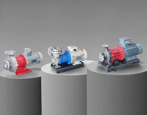





A mold temperature controller (MTC) is only as reliable as the pump inside it. The heater, PID logic, and stainless piping get most of the marketing attention, but on a real injection molding floor or die casting line, what fails first — and what stops the machine — is almost always the circulation pump. After supplying pumps to MTC builders in China, India, Germany, and Southeast Asia for more than a decade, we have seen the same pattern repeatedly: the wrong pump turns a high-spec mold temperature unit into a maintenance liability. The right one runs for years.
This guide is written from a pump manufacturer’s perspective — not a controller-maker’s. It covers how to specify, size, and seal a pump for a mold temperature controller across water-type, oil-type, and high-temperature die casting applications, with the engineering tradeoffs that OEM integrators actually face when selecting MTC pumps.
1. Understanding the Pump’s Role Inside a Mold Temperature Controller (MTC)
A mold temperature controller is, mechanically speaking, a closed thermal loop with five components: heater, heat exchanger, sensor, PID controller, and circulation pump. The MTC pump is the only moving part doing continuous work. Its job is straightforward — push the heat-transfer medium (water or thermal oil) through the mold’s cooling channels at a defined flow rate and pressure — but the operating envelope is brutal.
A typical MTC pump operates 18–24 hours a day, at temperatures between 90°C and 350°C, against constantly changing mold-side back pressure, sometimes through cooling channels narrower than 6 mm. Unlike a process pump on a chemical line that runs at a steady duty point, a mold temperature pump cycles through heating, cooling, and mold-change interruptions. It is also expected to handle air pockets every time a mold gets swapped.
This is why MTC pump selection cannot be reduced to choosing a pump with the right flow and head. The unit must also survive thermal shock, dry-start risk during mold change, and zero tolerance for fluid leakage in oil-based systems. Three pump categories handle this envelope in practice: vortex pumps (regenerative turbine type), centrifugal pumps, and magnetic-drive or canned-motor variants of both. Which one fits depends on the medium, the temperature, and how much leakage risk the OEM is willing to engineer around.
2. Specification Anatomy: How MTC Pump Parameters Translate to Real Mold Performance
The five parameters that actually decide whether an MTC pump performs are flow rate, head, working temperature, sealing method, and motor configuration. The first two are coupled by the pump curve; the others are independent design choices.
Flow rate (Q) is determined by the total cross-section of the mold’s cooling channels and the required temperature delta. A common rule of thumb on the molding-machine side: for every 1 kW of cooling load, you need roughly 3–15 L/min of water flow depending on the temperature differential you want to maintain across the mold — tight ΔT means more flow.
Head (H) is set by the cooling channel layout — long channels, sharp bends, and small-diameter cores all add friction loss. For high-cavity injection molds and die casting tools with multiple parallel circuits, head requirements often push past 40 m of water column, which is where a regular centrifugal pump starts losing efficiency and a vortex pump becomes the better fit.
The table below summarizes the working envelopes we typically specify into MTC OEM projects:
| Medium | Max Operating Temperature | Typical Flow (Q) | Typical Head (H) | Recommended Pump Type |
| Pressurized Water | 120 °C | 40–200 L/min | 15–25 m | Standard stainless centrifugal |
| Pressurized Water | 160 °C | 30–150 L/min | 25–50 m | High-head vortex pump |
| Pressurized Water | 180 °C | 30–120 L/min | 30–60 m | Magnetic-drive vortex pump |
| Thermal Oil | 200 °C | 30–200 L/min | 25–50 m | Hot oil centrifugal, mechanical seal |
| Thermal Oil | 320 °C (die casting) | 40–250 L/min | 30–60 m | Coupled hot oil pump or magnetic-drive |
| Thermal Oil | 400 °C | 30–200 L/min | 25–50 m | High-temperature coupled pump |
A pump performance curve always operates at the intersection of pump-side and system-side curves. The total flow rate through the mold’s cooling channels is what the MTC pump must supply; the total pressure drop in those channels is the minimum head the pump must provide. Plot the operating point — if it falls below the pump curve, the unit has spare capacity; if it falls above, the pump is undersized and the mold will not reach setpoint.
For a deeper look at how this works for centrifugal types specifically, see our industrial centrifugal pump efficiency guide.
3. Water-Type vs. Oil-Type MTC: Why the Pump Choice Changes With the Medium
Most mold temperature controller buyers see water-type and oil-type as a binary purchase decision driven by temperature. From inside the pump, it is more nuanced — water and thermal oil are two completely different fluids, and the pump must be specified accordingly.
Water-type MTC pumps operate in a pressurized closed loop. Standard 120 °C water-type units use copper-impeller or stainless centrifugal pumps with conventional mechanical seals — the cost-efficient default. Once the system has to push past 140 °C, water enters a regime where ordinary centrifugal pumps lose head rapidly and where any mechanical seal becomes a high-risk component because of thermal expansion mismatch. At 160 °C and above, the standard solution in the MTC industry is now a high-head vortex pump (also called a regenerative turbine pump), often built in stainless 304 or 316L. At 180 °C, OEMs almost always specify a magnetic-drive vortex pump to eliminate the dynamic seal entirely.
Oil-type MTC pumps handle thermal oil at 200–350 °C. Thermal oil has lower density, lower specific heat, and lower vapor pressure than water — but it also has a strong tendency to carbonize at hot spots, degrade seal elastomers, and ignite if it leaks onto a hot surface. The pump’s role here is not just hydraulic; it is a safety component. Standard oil-type units up to 200 °C can use hot oil centrifugal pumps with hard-faced mechanical seals. Above 230 °C, magnetic-drive or coupled hot oil pumps become the industry default. At 320 °C — the typical operating point of an aluminum die casting MTC — almost every modern unit uses a seal-less drive structure.
The reason is simple. A leak in a 100 °C water MTC is a housekeeping problem. A leak in a 320 °C oil MTC is a fire hazard. This is also why our customer in India for die casting equipment specifically requested MDW magnetic vortex pumps and WD-series welding pumps for mold temperature control loops — the zero-leakage requirement is non-negotiable in continuous casting cells.
For oil systems specifically, our team has covered selection in more depth in the hot oil transfer pump selection guide and the thermal oil circulation pump guide.
4. The Critical Sealing Question: Mechanical Seal vs. Magnetic Drive vs. Canned Motor for Mold Temperature Pumps
If you ask an experienced MTC service technician where 80% of pump failures originate, the answer is the shaft seal. The continuous thermal cycling, occasional dry-run during mold changes, and exposure to degraded heat-transfer fluid all attack the seal faces. Three structural options exist for handling this:
Mechanical seal pumps are the lowest-cost option and still dominate the entry-level MTC market. Hard-faced silicon carbide seal pairs can survive 180 °C water service if the seal flush is properly engineered. The downside is unavoidable: seals are wear components and they will fail. For an MTC manufacturer building 1,000 units a year, every unit shipped with a mechanical seal is a future warranty claim.
Magnetic-drive pumps transmit torque through a synchronous magnetic coupling across a static containment shell. There is no dynamic seal — the process fluid is fully enclosed. This is the standard solution for high-temperature water MTCs, oil-type MTCs above 230 °C, and any application where fluid leakage is unacceptable. Our MDH, MDW, and MDC series are all designed around this principle, and we have integrated them into MTC builds for clients in India, Germany, and South Korea.
Canned-motor pumps take the seal-less concept one step further: the motor rotor itself runs inside the process fluid, with a thin metallic can separating it from the stator. There is no coupling, no external shaft, no exposed bearing — the pump is hermetically sealed. We use this design in our PWH/PWD/PWM canned vortex pump series, which is specified into MTC units handling volatile heat-transfer fluids, low-temperature applications, and high-purity semiconductor coolant loops.
A simple decision matrix:
| Application | Recommended Seal Configuration |
| Water MTC, ≤ 120 °C, cost-sensitive | Mechanical seal, stainless centrifugal |
| Water MTC, 140–180 °C | Magnetic-drive vortex pump |
| Oil MTC, ≤ 200 °C, standard injection molding | Mechanical seal hot oil pump (with cooling chamber) |
| Oil MTC, 230–320 °C, die casting | Magnetic-drive or coupled hot oil pump |
| Oil MTC, > 320 °C, large die casting cells | Coupled high-temperature thermal oil pump |
| Cryogenic or fluorinated coolant MTC | Canned-motor vortex pump |
For the engineering details behind the magnetic-drive choice, our magnetic drive pump selection guide goes deeper into magnet-coupling losses, eddy currents, and decoupling torque.
5. Selecting a Vortex Pump for High-Head, Low-Flow Mold Temperature Pump Applications
Mold cooling channels rarely demand huge flow. What they demand is consistent head against fluctuating system resistance — and this is exactly where a vortex pump (regenerative turbine pump) outperforms a standard centrifugal design.
The physics: a vortex impeller transfers energy to the fluid in repeated stages around its periphery, achieving 4 to 8 times the head of a comparably sized centrifugal pump at the same RPM. For an MTC builder, this means you can deliver the 40–60 m head a high-cavity mold needs without specifying a larger motor or a multi-stage pump assembly. The pump stays compact, the motor footprint stays small, and the MTC cabinet stays serviceable.
Where vortex pumps belong inside a mold temperature pump system:
● High-head, low-flow MTCs feeding multi-circuit injection molds
● Pressurized hot-water MTCs in the 140–180 °C range
● Compact cabinet-style units with limited installation space
● Self-priming applications where the MTC can tolerate small amounts of entrained air
What to watch out for: vortex pumps are sensitive to abrasive particles. If the MTC operates with poorly filtered water (calcium scale, rust particles), the close clearance between the impeller and casing erodes quickly and head drops. For MTC OEMs, we typically recommend pairing the pump with a 50–80 mesh inlet strainer.
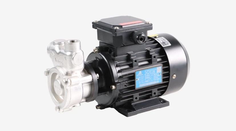
Our WD-series brass/stainless vortex pumps, WH-series stainless steel vortex pumps, and WK high-head vortex pumps are designed around this duty cycle. The WD vortex pump is the most commonly OEM-integrated unit into 120–160 °C water MTCs; the WH stainless steel vortex pump is used when corrosion resistance matters; the WK high-head vortex pump addresses cases above 40 m head. For 180 °C+ pressurized water service, the MDW magnetic vortex pump replaces the dynamic seal entirely.
A more complete technical treatment of vortex hydraulics is in our industrial vortex pump selection guide.
6. Matching Hot Oil Pumps to Die Casting MTC Systems and High-Temperature Oil Loops
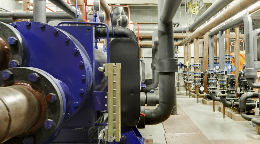
Die casting mold temperature control is the most demanding application a thermal oil pump will see. Operating temperatures sit at 280–320 °C continuously. The oil itself ages and viscosity drops as it carbonizes. The cycle includes constant flow changes as the die-cast tool opens, closes, and ejects. And the safety consequences of a leak are immediate.
Three structural choices for hot oil MTC pumps:
Coupled hot oil pumps use a long stub shaft and an air-cooled isolation chamber to keep the mechanical seal at a much lower temperature than the process fluid. The motor sits well away from the hot zone, often with an auxiliary fan. This is the industry standard for 300–400 °C thermal oil duty in continuous die casting cells. Our WRY-H coupled high-temperature thermal oil pump handles up to 400 °C with mechanical seal, and is the configuration most large MTC builders specify for aluminum die casting.
Magnetic-drive hot oil pumps eliminate the dynamic seal entirely. The cost is higher and the magnet-coupling can decouple under abrupt viscosity spikes, but for OEMs whose customers run lights-out die casting cells with no maintenance staff on shift, the zero-leakage guarantee is worth it.
Mechanical-seal hot oil centrifugal pumps are acceptable up to about 200 °C in oil-type MTCs intended for standard injection molding of engineered thermoplastics (PEEK, PPS, PEI). Above that range, the seal-and-cooling design needs to be re-engineered, or the pump should be replaced with a coupled or magnetic-drive version.
A direct technical comparison between centrifugal and gear-type hot oil pumps is in our centrifugal vs gear hot oil pump guide. For broader high-temperature applications, see our high-temperature pump solutions page.
7. A Practical Pump Sizing Method for MTC Engineers and OEM Integrators
The simplest way to size a mold temperature controller pump that does not lead to warranty headaches is to work backwards from the mold’s actual cooling load. Here is the protocol our application engineers use when an MTC builder sends us a sizing request:
Step 1 — Determine the cooling load. Use the basic heat balance: Q = m × Cp × ΔT, where Q is heat to be removed in kW, m is the mass flow rate, Cp is the specific heat of the medium (4.18 kJ/kg·K for water, ~2.1 kJ/kg·K for typical thermal oil), and ΔT is the temperature differential across the mold supply and return.
Step 2 — Convert to volumetric flow. For water, the working formula is Q [L/min] ≈ 14.3 × kW / ΔT[°C]. A 10 kW load at a 3 °C delta-T therefore needs roughly 48 L/min. Apply a 1.5–2× multiplier on top to guarantee turbulent flow in narrow cooling channels — laminar flow kills heat transfer efficiency.
Step 3 — Calculate the system head. Sum the static head, the friction losses in the supply and return lines, and the pressure drop across the mold’s cooling channels. The last item dominates — for multi-circuit injection molds with cores smaller than 8 mm, expect 2–4 bar pressure drop alone.
Step 4 — Add safety margin. Specify pump head 15–25% above the calculated system head. This accommodates scale buildup, valve adjustments, and cooling-channel restriction over time.
Step 5 — Match temperature and seal class. Cross-check against the medium/temperature table in section 2 and the sealing matrix in section 4.
Step 6 — Validate with a real performance curve. Ask the pump supplier for the actual factory test curve (not the catalog curve) at the duty point. The two are not always identical.
For MTC builders who want this conversation pre-engineered, we provide application-condition forms that capture all six steps in a one-page format. Many of our OEM partners — including builders shipping into the European mold-temperature unit market under the EU pump ecodesign regulations — use this method to standardize their pump procurement.
8. Common Mold Temperature Pump Failures and How OEM Design Choices Prevent Them
After more than a decade of MTC OEM work, the failure modes we see fall into five repeatable categories. Each one is preventable with the right design choice upstream:
Pump overload during mold change. When an operator swaps molds without venting the system, the pump suction line fills with air. The motor draws full current, the impeller cavitates, and bearing temperature spikes within minutes. Solution: specify a pump with built-in air-handling capability (vortex pumps tolerate small air bubbles better than centrifugal designs) and integrate a low-flow alarm into the MTC controller.
Mechanical seal failure on oil-side MTCs. Thermal oil degrades elastomers and the seal flush chamber loses cooling over time. Within 6,000–8,000 operating hours, a hard-faced mechanical seal on a 250 °C oil pump will start leaking. Solution: design the MTC around a magnetic-drive or coupled pump from the start, and accept the higher unit cost as warranty insurance.
Wear-ring erosion from poor water quality. Calcium scale and rust particles erode the close clearances inside a vortex pump’s casing. Within months, head drops and the MTC can no longer hit setpoint. Solution: specify a 50–80 mesh inlet strainer as standard, and recommend descaling intervals in the user manual. For deeper background on water-quality effects, see the preventing pump cavitation guide.
Magnet decoupling. Magnetic-drive pumps can lose torque transmission if the viscosity spikes suddenly — for example, when cold oil sits in the system during a cold start. The driven magnet stops, the driver magnet keeps spinning, and the pump produces no flow. Solution: specify a soft-start motor, an oil pre-heater interlock, and a magnet rated for 20–30% torque margin above the cold-start duty.
Motor burnout from over-temperature. When the mold-side loop blocks completely, flow stops, and the pump body temperature rises rapidly. Without a thermal cutout, the motor windings burn within 10–15 minutes. Solution: integrate a motor PTC sensor and a pump-body thermocouple into the MTC’s PID logic.
The chemical pump parts lifespan and maintenance guide covers some of these failure modes in more detail, including service interval planning.
9. Why MTC OEMs Across Asia and Europe Specify Aulank Pumps
We have spent 17+ years building pumps for industrial fluid transfer under extreme conditions, and mold temperature control is one of our deepest verticals. Our active OEM partners include die casting equipment makers in India running 320 °C thermal oil loops, German lithium-battery separator coating lines using MDH magnetic vortex pumps, semiconductor chiller builders in South Korea and Taiwan, and welding equipment manufacturers in Russia and Turkey.
What an MTC builder gets from us specifically:
● A complete pump matrix for MTC duty — WD/WH/WK/WL/WM vortex pumps for 120–200 °C water service, MDH/MDW/MDS/MDK magnetic vortex pumps for sealing-critical applications, WRY-H coupled hot oil pumps for 300–400 °C die casting, PWH/PWD/PWM canned vortex pumps for zero-emission service.
● OEM customization — special voltage and frequency (110V, 220V, 380V, 415V, 50/60Hz, DC), explosion-proof motor configurations, custom flange dimensions to match existing MTC piping, structural modifications for non-standard cabinet layouts.
● Synchronous permanent magnet drive technology — one of our 10 core technologies, used to reduce motor losses and improve thermal efficiency in continuous-duty MTC pumps.
● Documented quality control — every unit ships with inspection records and parameter test data, and our magnetic drive pumps carry TÜV CE certification.
● A factory in Kunshan with 10,000+ m² of production and testing capacity, supporting multi-model, small-batch, and customized pump runs without the lead-time penalty that comes with project pumps from European suppliers.
If you are an MTC builder evaluating a pump source, the practical starting point is to send us your application conditions — medium, temperature, flow, head, mold layout, and seal preference — and our engineering team will return a configuration recommendation and a quote within two business days.
Get a Custom MTC Pump Configuration
Whether you are standardizing pump procurement for a new line of mold temperature controllers or replacing a problematic pump on an existing platform, our engineering team can match the right pump architecture to your operating conditions.
Talk to our team: Contact Aulank | WhatsApp: +86 13773157367 | Email: info@aulankpump.com
Browse the full range of pumps for mold temperature controllers and other thermal applications: