





Semiconductor manufacturing runs on temperature control. Every step in a leading-edge fab — EUV lithography, CMP, plasma etch, CVD, ion implant, optical metrology — depends on holding tool-side fluids at a stable setpoint, often within ±0.1 °C. The chillers and TCUs that maintain that stability are sold as finished equipment, but the component that actually moves the coolant through them is a pump. When that pump fails, or pulsates, or contaminates the loop, the wafer either scraps or comes back from inspection with subtle defects no one wants to debug. We have shipped magnetic-drive pumps into semiconductor chiller and fluorinated-coolant projects in Taiwan, South Korea, and mainland China for over a decade, including a long-running Taiwan project supplying MDW series pumps with synchronous permanent magnet motors customized specifically for sub-zero PFPE coolant transfer.
This guide covers how to select a pump for semiconductor coolant service in 2026 — a year in which the industry is simultaneously building 18+ new 300mm fabs, pushing process temperatures further toward −80 °C, and migrating away from 3M’s discontinued Fluorinert and Novec fluids onto Galden PFPE and third-party HFE replacements. The pump choices that worked five years ago are not automatically the right choices today.

1. The Semiconductor Cooling Pump Challenge: From EUV Lithography to CMP and Etch
A modern fab has more than a dozen tool categories that need active liquid cooling. Each one has a different fluid, a different temperature setpoint, and a different tolerance for pump-induced disturbances. Understanding the full map is the precondition for sensible pump specification:
● EUV lithography source and scanner cooling — −20 °C to +25 °C, PFPE or glycol-water mix, extremely tight pulsation budget because optical alignment drifts with vibration.
● Wet bench & CMP (Chemical Mechanical Polishing) — temperature-controlled slurry and cleaning chemistries, often 20–40 °C, with high purity requirements (no metal ions into the slurry path).
● Plasma etch and PECVD reactor chuck cooling — −40 °C to +80 °C, fluorinated PFPE coolant directly contacting electrostatic chucks and showerheads.
● Ion implant beamline cooling — water-glycol typically, but secondary loops for high-energy implanters use PFPE.
● Inspection & metrology tools — optical inspection, e-beam metrology, mask inspection. ±0.1 °C control with near-zero flow pulsation; this is where pump architecture matters most.
● Test & burn-in — thermal shock chambers cycling chips between −65 °C and +155 °C in two-phase Fluorinert/Galden baths.
● Cryogenic process steps — cold etching at −100 °C, sample preheating to −196 °C with liquid nitrogen for advanced 3D NAND and HBM stacking.
● Sub-fab utility loops — process cooling water (PCW), ultrapure water, slurry reclaim. Lower precision, higher flow.
Five engineering constraints cut across all of these stations: zero leakage to protect cleanroom air and expensive PFPE inventory, ultra-low metal ion contamination of the fluid, pulsation-free flow at the lithography and inspection tools, the ability to operate continuously at temperatures from −196 °C to +290 °C, and chemical compatibility with fluorinated heat-transfer fluids whose properties differ sharply from water. No single pump architecture covers all five at once. What works is a portfolio matched to the station.

2. Fluorinated Coolant Chemistry: Galden PFPE, Fluorinert FC, and HFE Compared
Before specifying a pump, you have to know the fluid. The three families that dominate semiconductor cooling are perfluoropolyethers (PFPE, sold under the Galden brand by Syensqo/former Solvay), perfluorocarbons (PFC, sold under the Fluorinert brand by 3M), and hydrofluoroethers (HFE, sold by 3M as Novec). They look similar from a process engineer’s perspective — clear, dielectric, inert — but they pump very differently.
Key properties that matter for pump selection:
| Coolant Family | Typical Brand | Operating Range | Density at 25°C | Viscosity at −40°C | Pump-Side Notes |
| PFPE | Galden HT55–HT270 | −70 to +290 °C | 1.7–1.9 g/cm³ | 5–20 cP (HT55–HT135) | Industry standard for chiller/TCU service; replaces discontinued 3M fluids |
| PFC | Fluorinert FC-3283 / FC-40 / FC-72 | +30 to +215 °C | 1.7–1.9 g/cm³ | N/A (frozen) | 3M production ended Oct 2024 (FC-3283) through end of 2025 |
| HFE | Novec 7100/7200/7300/7500 | −135 to +260 °C | 1.4–1.6 g/cm³ | 0.4–1.5 cP | Lower GWP than PFC/PFPE; 3M ending production; HFE alternates from TMC/BestSolv |
| Glycol-water | 50/50 ethylene glycol | −35 to +105 °C | 1.07 g/cm³ | 50–200 cP | Cheap, but cannot reach the temperatures advanced nodes require |
Three things to notice. First, Galden PFPE and Fluorinert PFC are roughly twice as dense as water — a pump sized for water service will under-deliver on PFPE because the same hydraulic horsepower moves less volume. Second, the viscosity of Galden rises sharply as temperature drops; below −50 °C even the low-boiling HT55 grade approaches the 20 cP limit at which centrifugal hydraulics start losing efficiency. Third, the fluids cost between USD 200 and USD 500 per kilogram — every leak is an inventory loss, every contaminated liter is reclamation work, and every drop on the cleanroom floor triggers an HSE incident.
3. The 3M Exit: Why Pump Specifications Are Being Re-Examined Across the Industry
In December 2022, 3M announced it would exit the per- and polyfluoroalkyl substances (PFAS) business entirely by the end of 2025. The first concrete cut came in October 2024 with the discontinuation of Fluorinert FC-3283, the workhorse single-phase coolant used in countless semiconductor chillers and test-and-burn-in stations. By the end of 2025, the full Novec and Fluorinert lines had ended production. Fab planning groups, OEM TCU builders, and pump suppliers like us have all been working through the consequences.
For pump selection, the consequences are concrete:
● Migration toward Galden PFPE changes the hydraulic operating point. PFPE has higher viscosity at the cold end of the operating range than the Fluorinert grades it replaces. A pump curve published against FC-3283 service at −40 °C is no longer valid against Galden HT80 at the same temperature. Existing TCUs that worked fine on FC fluids can run away from their setpoint after a refill swap.
● HFE alternatives have lower density but higher vapor pressure. Novec 7100 boils at +61 °C; if the pump operates near that temperature, NPSH margin becomes the critical specification rather than head. Cavitation appears earlier in the duty cycle than it does on PFPE.
● Reclaimed and third-party fluids introduce purity variability. TMC, BestSolv, and other vendors offer FC-3283 and Novec replacements, including reclaimed material. The purity, particle count, and dissolved metal content vary batch to batch. A pump with hardened or non-metallic internal liners protects yield in a way that a standard stainless pump cannot.
● PFAS regulatory pressure is still tightening. REACH restrictions on long-chain PFAS, US EPA enforcement on PFOA/PFOS, and proposed broader fluorinated-compound rules continue to push fabs toward zero-emission containment. Mechanical-seal pumps in PFPE service are no longer just a maintenance liability — they are an environmental compliance risk. We covered the broader regulatory picture in our PFAS regulations and chemical pump requirements guide.
4. Engineering for Ultra-Low Temperature: Why Pumping at −80 °C Is Different
Most pump catalogs publish performance curves against 20 °C water. Semiconductor cooling pumps operate in a regime where that data is almost useless. Three thermal effects dominate at sub-zero operation:
Thermal contraction and clearance loss
Stainless steel contracts roughly 0.3% from room temperature to −80 °C, and another 0.1% down to −196 °C. Plastic components contract more. If a pump is built with tight clearances at 20 °C, those clearances vanish at cryogenic temperatures and metal-to-metal contact follows within seconds. The design counter-measure is asymmetric clearance specification — a pump intended for −80 °C service is machined with running clearances at room temperature that look loose, but tighten to the correct fit at operating temperature.
Magnet performance vs. temperature
Neodymium-iron-boron (NdFeB) magnets, the default choice for room-temperature mag-drive pumps, lose magnetic flux as temperature drops below their design point and recover when warmed. They do not demagnetize at cryogenic temperatures the way they do above their Curie point, but the torque coupling can drop by 10–20% at −80 °C. For ultra-low temperature service we typically over-size the magnet coupling by 25–30% on top of the cold-start viscosity penalty, and on the AYDH liquid nitrogen pump we use specialized cryogenic-rated magnet stacks that hold torque down to −196 °C.
Bearing lubrication in a non-lubricating fluid
Magnetic-drive pumps rely on the process fluid to lubricate the internal silicon-carbide or PEEK bearings. Fluorinated coolants have very low surface tension and almost no boundary lubrication, especially when cold. The bearing-to-shaft clearances and bearing material choice must be matched to the specific coolant. Silicon carbide on silicon carbide works reliably for PFPE down to −70 °C; below that range, PEEK polymer bearings outperform SiC because they tolerate marginal lubrication better. For our AYDH magnetic liquid nitrogen pump, the bearing system is purpose-engineered for −196 °C operation with deep-cryogenic-treated components and ceramic isolation shells.

5. Why Magnetic Drive Architecture Is Mandatory for Fluorinated Coolant Service
For semiconductor cooling, the mechanical-seal pump is effectively obsolete. Three reasons drive this:
● Fluorinated coolant inventory is too expensive to leak. A 500-liter chiller charge of Galden HT135 represents USD 100,000–USD 250,000 of fluid inventory. A shaft-seal leak that drops 1% of the charge per month is a five- to six-figure annual loss before any HSE or cleanroom impact. The capital cost differential of magnetic-drive over mechanical-seal is recovered in months.
● Cleanroom HSE protocols cannot tolerate fugitive emissions. PFPE droplets in cleanroom air do not just contaminate wafers — they trigger immediate facility shutdowns. Sealless construction is increasingly written directly into TCU and chiller equipment specifications by major foundry buyers.
● Continuous-duty 24/7 service has no maintenance window. A semiconductor fab runs every wafer-producing minute it can. Mechanical seals degrade predictably, and their failure schedule does not align with the fab’s. Magnetic-drive pumps with silicon-carbide bearings have demonstrated 50,000+ hour MTBF in cleanroom service, which means a planned bearing change aligns with a fab shutdown rather than triggering one.
For deeper engineering background on the architecture, including magnet selection, eddy current losses in metallic containment shells, and decoupling torque, see our industrial magnetic drive pump selection guide. For continuous-duty applications where even a stuffed-shell static O-ring is unacceptable, the canned-motor variant goes one step further — the motor rotor runs inside the process fluid behind a thin metallic can, eliminating the magnet coupling entirely. Our canned motor pump technology guide covers the three structural variants of seal-less drive.

6. Pulsation Control for EUV, Optical Metrology, and Wafer Inspection Tools
Of all the constraints on a semiconductor cooling pump, the one that catches first-time integrators by surprise is pulsation. An EUV scanner’s reticle stage holds positional alignment to single-nanometer tolerance. The optical column of an e-beam inspection tool resolves features below 5 nm. Any flow-induced vibration in the cooling loop transmits mechanical noise into the optical or mechanical subsystem and degrades resolution. Tool builders specify the pump as a vibration source, not just as a flow-and-head component.
Three pump-side causes of unwanted pulsation in this service:
● Gear-tooth pulsation in external gear pumps — small periodic flow variations as gear teeth mesh and unmesh.
● Reciprocating motion in piston or diaphragm pumps — large periodic flow surges between strokes; unacceptable for any precision application.
● Cavitation pulsation near the NPSH limit — irregular flow as vapor bubbles form and collapse, particularly on HFE service where the boiling point is close to the operating temperature.
Configurations we specify for low-pulsation semiconductor service:
● Magnetic-drive vortex (regenerative turbine) pumps. Our MDW and MDS series produce nearly continuous flow with peak-to-peak pulsation typically below 2% at rated duty point. The regenerative turbine impeller transfers energy in many small stages around its periphery rather than in discrete blade passes, which inherently smooths the discharge. This is the configuration we have shipped into multiple Taiwan and South Korean semiconductor chiller projects.
● Brushless DC motor drive with closed-loop speed control. Synchronous permanent magnet motors with VFD or sensored DC control hold rotational speed within ±0.5%, eliminating speed-induced flow ripple. This is one of our 10 core technologies and is standard on our semiconductor-spec pumps.
● Discharge accumulator or bladder dampener. For the most pulsation-sensitive stations (EUV scanners, e-beam columns), a small accumulator placed at the pump discharge brings residual pulsation below 0.5% peak-to-peak. This is a system-level addition rather than a pump feature, but worth specifying.
7. Materials and Wetted Parts: 316L, PTFE, PEEK, and Ceramic Bearings
Fluorinated coolants are chemically inert toward almost everything, but the contamination flowing into the fab from the pump is not the coolant — it is whatever the coolant scrubs off the wetted surfaces over thousands of operating hours. The materials specification is therefore driven by contamination control, not by chemical compatibility:
● 316L stainless steel. The default wetted material for chiller-grade semiconductor pumps. Mirror-polished to Ra 0.2 µm or better to minimize particle shedding. Acceptable for PFPE service over decades; not acceptable for HF-bearing process fluids (which is why fab utility pumps and electrolyte/CMP pumps must move to fluoropolymer-lined construction).
● PTFE / PFA fluoropolymer lining. For ultra-pure service or for chemistries that include trace HF or acidic species (CMP, wet bench, electrolyte recovery), full PTFE-lined construction eliminates metal-ion leaching to ppb levels. Our AMC-F PTFE-lined magnetic drive pump is built for this duty class.
● PEEK polymer bearings and containment shell components. Selected for sub-zero service where thermal contraction makes ceramic shells brittle. PEEK shows excellent cryogenic toughness and chemical inertness; downside is lower temperature ceiling (typically ≤ 200 °C).
● Sintered silicon carbide bearings. Industry-standard for room-temperature mag-drive pump bearings. Excellent hardness, near-zero wear, universal chemical compatibility. Less forgiving than PEEK at marginal lubrication; pair with dry-run protection if used in services where flow may briefly drop to zero.
● Ceramic isolation shells. Non-metallic containment shells eliminate eddy-current losses (no induced heating in the shell from the rotating magnetic field), which matters at cryogenic temperatures where even a few watts of parasitic heat can disturb the loop. Ceramic shells are standard on our AYDH liquid nitrogen pump.
For mainstream PFPE chiller service, the typical configuration is 316L wetted parts with mirror polish, silicon-carbide bearings, and a thin metallic containment shell. For HF-bearing or wet-bench duty, full PTFE lining. For sub-zero precision metrology, ceramic shell with PEEK bearings. The decision tree maps cleanly to the station, not to a single “best” configuration.

8. A Sizing Method for Semiconductor Chiller and TCU Pumps
Sizing a pump for semiconductor coolant service is a six-step protocol. The shortcut version below is what our application engineers use when an OEM TCU builder or fab engineering team sends us a specification:
● Step 1 — Identify the coolant and its density at the cold operating temperature. Galden HT80 at −40 °C has density ~1.92 g/cm³. Pump hydraulic horsepower scales with density, so a 1.5 kW water pump becomes a 2.9 kW PFPE pump at the same flow and head.
● Step 2 — Calculate cooling load and required flow. For a tool dissipating Q kW with a permitted ΔT across the loop, the volumetric flow follows V[L/min] = Q[kW] / (ρ[kg/L] × Cp[kJ/kg·K] × ΔT[K] / 60). Galden HT80 has Cp ~0.97 kJ/kg·K; for a 5 kW tool load at 3 °C ΔT this works out to roughly 53 L/min. Apply a 1.3× multiplier for turn-down margin.
● Step 3 — Compute system head. Sum static head, pipeline friction (account for the higher viscosity of cold PFPE), and pressure drop across the tool-side cold plate. For semiconductor TCUs feeding compact tool plates, total head is commonly 3–8 bar.
● Step 4 — Check NPSH margin. At low temperatures Galden has very low vapor pressure and NPSH is rarely limiting; at HFE service near its boiling point, NPSH dominates. Specify suction-side conditions explicitly and pick a pump rated for the available NPSH plus 30% margin.
● Step 5 — Match the pump architecture to pulsation tolerance. For lithography, metrology, and inspection: regenerative-turbine magnetic vortex pump. For wet-bench and CMP: PTFE-lined magnetic pump. For test & burn-in: standard 316L mag-drive vortex. For cryogenic process steps: AYDH liquid nitrogen variant.
● Step 6 — Validate with a sample fluid test. Catalog curves are produced on water. For semiconductor-critical applications, ask the supplier to test on the actual coolant grade at the actual operating temperature, with measured pulsation and contamination data. We provide this validation for any Galden / Fluorinert / HFE service quote on request.
9. Aulank Semiconductor Pump Portfolio: MDW, AYDH, PWH, AMC-F
We have been supplying magnetic-drive and canned-motor pumps to the semiconductor sector since 2015. Active projects include a Taiwan semiconductor customer running MDW series pumps with custom synchronous permanent magnet motors for low-temperature fluorinated liquid transfer, a South Korean semiconductor chiller equipment builder using MDW units for chiller integration testing, and multiple mainland Chinese fab utility and tool-OEM integrators across CMP, wet bench, and cryogenic process steps. The portfolio we typically recommend across a semiconductor fab pump bill of materials:
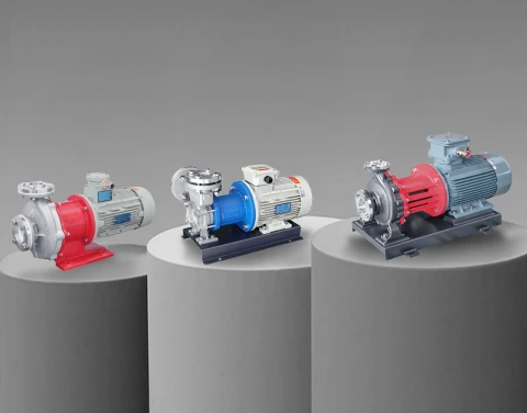
● MDW stainless steel vortex magnetic pump — the workhorse for chiller and TCU loops on Galden HT55–HT135 and equivalent PFPE fluids. 304/316L wetted parts, mirror polish, −40 to +200 °C standard. The unit we have shipped most often into Taiwan and South Korean fab cooling projects.
● MDS stainless steel vortex magnetic drive pump — same hydraulic family as MDW with higher flow capability for larger central chiller plants and sub-fab utility loops.
● AYDH magnetic liquid nitrogen pump — cryogenic-rated for service down to −196 °C. Used in liquid nitrogen circulation, cold etching tools, freeze-drying, and ultra-low temperature wafer process steps. Deep-cryogenic-treated pump body and ceramic isolation shell.
● PWH/PWD/PWM canned vortex pump — the canned-motor variant for high-purity continuous service where even static O-rings are an exposure path. Common in PFPE reclaim and recovery loops, VOC recovery, and process loops at the highest fab purity classes.
● AMC-F PTFE-lined magnetic drive pump — full PTFE-lined wetted parts for wet bench, CMP slurry, electrolyte, and any duty where HF-bearing or acidic chemistry would attack 316L. Metal-ion contamination held to ppb levels.
Customization the semiconductor sector typically asks for: synchronous permanent-magnet motors instead of standard induction (improves coupling efficiency and reduces pulsation), DC and 24 V variants for tool-integrated chillers, cleanroom-compatible coating and packaging, custom flange dimensions to match existing TCU footprint, explosion-proof variants for HFE and DMC vapor zones, and full inspection records with material traceability for fab qualification.
Our magnetic vortex pumps carry TÜV CE certification, our wider product range complies with ISO 9001 and CE quality requirements, and we hold 50+ technical patents covering the synchronous permanent-magnet drive structure, cryogenic magnet coupling, and shielded vortex hydraulics used in this product family.
Get a Semiconductor Cooling Pump Configuration
Whether you are an OEM building chillers, TCUs, or wafer-processing tools, or an end-user fab specifying pumps for a new line or a PFPE migration project, our engineering team can match the right magnetic-drive pump architecture to each station and validate it against your actual coolant grade and operating conditions.
Talk to our team: Contact Aulank | WhatsApp: +86 13773157367 | Email: info@aulankpump.com
Browse the relevant product and solution pages: