


Air cooling ends somewhere around 20 kW per rack. AI racks already run past 100 kW, and announced GPU systems point toward 600 kW per rack within a few product cycles. Liquid moves roughly 3,000 times more heat than air per unit volume, which is why every serious AI deployment now includes a liquid cooling loop, and why one piece of equipment sits at the center of all of them: the coolant distribution unit, or CDU. The CDU decides what temperature, flow, and pressure actually reach the cold plates on the processors, and it keeps the facility's water away from the sensitive electronics loop. This guide explains what a CDU is, how the two-loop architecture works, what lives inside the unit, the types on the market, and the specifications that matter when reading a datasheet.
What a Coolant Distribution Unit Actually Does
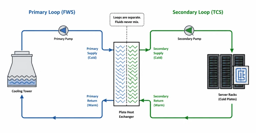
A CDU performs two jobs at once. First, it isolates: the clean coolant circulating to the IT equipment never mixes with the facility water, because the two loops meet only across a plate heat exchanger. Second, it controls: pumps, valves, and sensors inside the unit hold the technology-side coolant at exactly the flow, temperature, and pressure the cold plates require, adjusting in real time as AI workloads swing. AI training loads can shift power draw dramatically in milliseconds, and the CDU is the component that absorbs those swings hydraulically so the chips see stable cooling. Think of it as the managed boundary between the building and the rack: everything the facility provides arrives on one side, and everything the servers need leaves from the other.
The Two-Loop Architecture: FWS and TCS
Direct-to-chip liquid cooling runs on two closed loops connected through the CDU's heat exchanger:
- Primary loop (Facility Water System, FWS): the building side, fed by chillers, cooling towers, or dry coolers. It carries heat away from the CDU to the facility's heat rejection plant. Water quality on this side is whatever the building provides.
- Secondary loop (Technology Cooling System, TCS): the equipment side, circulating clean, treated coolant, typically a 20 to 35 percent water-glycol mixture, from the CDU through row manifolds, rack manifolds, and finally the cold plates mounted on CPUs, GPUs, memory, and power modules.
The separation matters for three reasons. It protects the electronics loop from facility water contamination. It lets the secondary loop run at its own pressure, independent of building hydraulics. And it allows precise supply temperature control, including holding the coolant above the room dew point to eliminate condensation risk on cold plates and manifolds.
Inside the Box: Core CDU Components
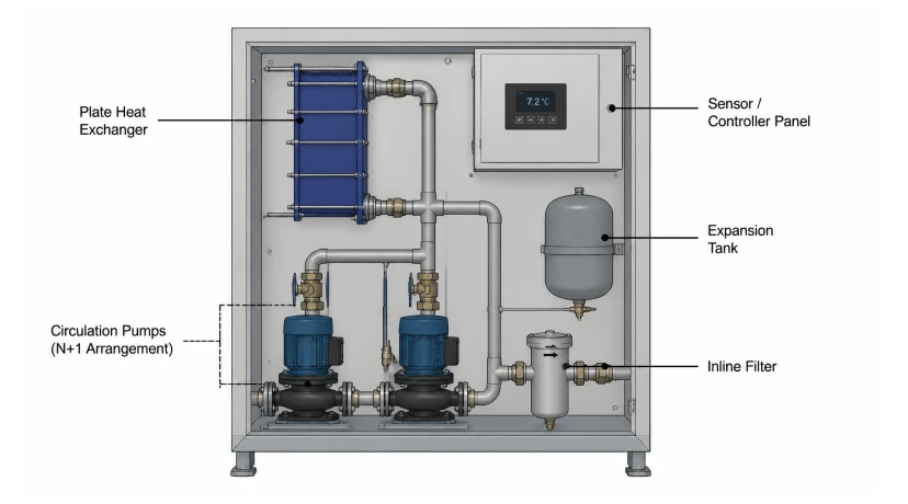
Plate heat exchanger
The thermal bridge between the loops. CDU capacity ratings are always quoted at an approach temperature, the difference between the secondary supply and the primary supply. A unit rated 300 kW at a 7°C approach delivers that capacity only when the facility water arrives cold enough; the same hardware delivers less at a wider approach. Reading capacity without reading the approach temperature is the most common datasheet mistake.
Circulation pumps
The pumps drive the secondary loop and define its hydraulic character. Commercial CDUs run them in N+1 or better redundancy with automatic switchover, because a stopped pump means an overheating rack within seconds. Variable-speed drives match flow to real-time load, cutting energy during idle periods. The pump must hold stable pressure across the loop's full operating range, from a single rack at partial load to a full row at peak, while pushing glycol-blended coolant through cold plates whose microchannels create substantial pressure drop.
Expansion tank, filtration, and sensors
The expansion tank absorbs coolant volume changes as the loop heats and cools and provides the fill point for commissioning. Inline filtration protects cold plate microchannels from debris. Sensor packages monitor supply and return temperature, differential pressure, and flow on both loops, with optional conductivity and turbidity monitoring for coolant health.
Controls
The controller closes the loop between sensors and hardware: modulating pump speed and control valves to hold supply temperature, watching for leaks, managing anti-condensation logic, and reporting upstream over Modbus, BACnet, or SNMP to the data center management system.
Redundancy as a design baseline
AI training runs cost thousands of dollars per hour in reserved compute, and a cooling interruption ends the run. CDUs therefore treat every active component as a failure candidate: pumps in N+1 configuration with automatic switchover, dual power feeds, redundant sensors, and controllers that ride through a single fault without dropping the loop. Maintenance follows the same logic. Better units allow pump and filter service without draining the secondary loop or taking racks offline, which turns the CDU from a single point of failure into a serviceable subsystem with uptime measured against the servers it feeds.
CDU Types and Where Each Fits
| Type | Heat rejection | Typical capacity | Best fit |
|---|---|---|---|
| Liquid-to-liquid (L2L), in-rack | Facility water loop | 50 to 300 kW | High-density GPU racks with facility water available |
| Liquid-to-liquid (L2L), row-based | Facility water loop | 300 kW to 1.8 MW | Rows of AI racks, hyperscale and colocation halls |
| Liquid-to-air (L2A) | Room air | Up to ~100 kW | Retrofits and edge sites without facility water piping |
L2L units deliver the best thermal performance and efficiency wherever a facility water loop exists or can be justified. L2A units trade capacity for deployment freedom: no piping to the building, just power and room air, which makes them the entry point for liquid cooling in existing enterprise rooms.
The Pump's View: What the Secondary Loop Demands
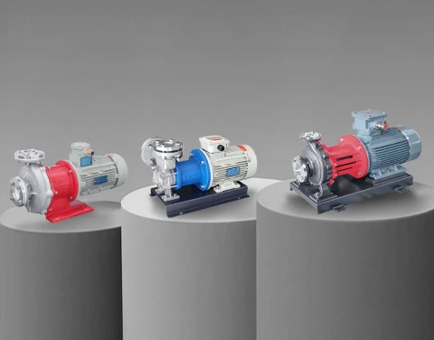
From a pump engineering standpoint, the TCS loop is a specific and demanding duty. The coolant is a water-glycol blend whose viscosity climbs at low temperature, so pump curves need derating at the cold end. Cold plate microchannels, quick-disconnects, and manifold networks stack up resistance, requiring stable head at moderate flow, where pressure capability outweighs volume. Continuous 24/7 operation at variable speed rules out anything with a wearing shaft seal, because a seal leak inside a data hall threatens equipment worth orders of magnitude more than the pump. Seal-less magnetic drive circulation pumps with stainless wetted paths, such as the MDW series, match this duty: zero leak path, stable low-flow pressure, and forward/reverse capability that simplifies loop filling, draining, and purging during commissioning and service. The selection logic is covered in detail in the AI data center liquid cooling pump selection guide.
CDU Cooling in the Wider Liquid Cooling Landscape
The CDU-based direct-to-chip approach dominates current AI deployments, yet it shares the field with other architectures:
| Technology | Rack heat captured by liquid | Server modification | Pump role |
|---|---|---|---|
| CDU direct-to-chip | 60 to 80% | Cold plates on CPU/GPU | Secondary loop circulation driver |
| Rear-door heat exchanger | 40 to 60% | None | Facility water circulation |
| Single-phase immersion | Up to 98% | Bare boards in dielectric tank | Dielectric fluid circulation |
| Two-phase immersion | Up to 98% | Bare boards in boiling fluid | Low-duty makeup and condensate return |
Direct-to-chip leads because it keeps standard server chassis, standard maintenance procedures, and OEM warranties intact. The residual 20 to 40 percent of rack heat from memory, storage, and power supplies still leaves by air, so most CDU deployments run hybrid with supplemental air cooling.
Reading a CDU Datasheet: The Numbers That Matter
- Cooling capacity at stated approach temperature: never compare capacities quoted at different approaches.
- Secondary flow rate and available pressure: confirm the unit clears your loop's pressure drop at design flow, including manifolds, quick-disconnects, and cold plates.
- Pump redundancy and switchover: N+1 minimum, with automatic failover and hot serviceability.
- Coolant supply temperature range and dew point control: anti-condensation logic is mandatory for cold-supply operation.
- Fluid compatibility: glycol concentration range and wetted materials on both loops.
- Controls and integration: protocol support, alarm logic, and remote management compatibility with your DCIM.
Aulank Pump manufactures seal-less vortex magnetic drive circulation pumps for CDU and secondary loop duty in AI data centers, with zero-leakage containment, stable low-flow pressure, and media ratings from −196°C to +400°C. If you are building or specifying a CDU and need the circulation pump matched to your loop hydraulics, send us your flow and pressure drop data. Contact us for engineering support.