


In process manufacturing, centrifugal pumps are the foundational drivers of continuous fluid distribution. However, a standard rotodynamic pump frequently encounters severe operating bottlenecks when integrated into complex chemical lines, high-temperature thermal loops, or systems with variable system pressures. Issues like mechanical seal degradation, rapid impeller erosion, and hydraulic decoupling directly lead to unplanned plant downtime.
Maximizing fluid system performance requires looking beyond the pump unit itself. System engineers must analyze the dynamic interaction between the fluid's physical properties and the facility's piping architecture. This technical guide delivers field-proven solutions for optimizing centrifugal pump systems, ensuring zero leakage, and maintaining hydraulic stability under harsh industrial conditions.

1. Correcting Hydraulic Mismatch: Aligning the Pump Curve with System Friction
A common driver of poor industrial efficiency is operating a rotodynamic machine too far to the left or right of its Best Efficiency Point (BEP).
When a pump runs far off-BEP, it generates strong internal radial forces that deflect the shaft, destroying mechanical seals and bearings in short order.
● The Solution: System design must start by calculating the total system friction curve—accounting for static lift, pipe runtime, valves, and fittings. For applications with shifting flow requirements, installing a Variable Frequency Drive (VFD) allows the pump's rotational speed to adjust dynamically. This shifts the equipment's performance curve to meet actual system demand without energy-wasting throttling.

2. Preventing Suction Cavitation: Managing the NPSH Safety Margin
Cavitation occurs when local static pressure at the impeller inlet drops below the fluid's vapor pressure, causing vapor bubbles to form and violently collapse against the metal surfaces. This micro-impact quickly destroys impellers and creates severe system vibrations.
● The Solution: Technicians must verify that the Net Positive Suction Head Available ($NPSH_a$) from the piping layout maintains a safety margin at least 0.5 to 1.0 meters higher than the Net Positive Suction Head Required ($NPSH_r$) listed on the manufacturer's curve. If your physical layout restricts suction pressure, look to specialized self-priming centrifugal designs or peripheral vortex configurations. These handle entrained air and maintain suction lift without needing external vacuum priming setups.

3. Eliminating Fugitive Emissions: Upgrading to Sealless Containment
Traditional dynamic mechanical seals account for up to 70% of all unplanned centrifugal pump maintenance. Frictional heat and chemical crystallization score seal faces, leading to fluid leaks that threaten plant safety.
Sealless Engineering Options
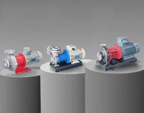
● Magnetic Drive Centrifugal Pumps: These replace the open drive shaft with a static containment shell. Power transfers through an outer magnet ring to an inner magnet assembly attached to the impeller. This forms a completely sealed liquid end that ensures zero leakage of volatile organic compounds (VOCs) or aggressive acids.
● Canned Motor Systems: Motor and hydraulic elements are enclosed within a single hermetic casing. This setup is highly effective for high-pressure, extreme-temperature processes where aligning an external motor coupling is impractical.

4. Viscosity Thresholds: When to Move Beyond Rotodynamic Systems
Centrifugal pumps depend on high-velocity fluid acceleration to build pressure. When fluid viscosity climbs above 100 Centistokes (cSt), internal fluid friction creates severe viscous drag inside the pump casing.
| Fluid Kinematic Viscosity | Recommended Pump Architecture | Expected Hydraulic Performance |
| 0.1 cSt to 100 cSt | Standard / Stamped Stainless Centrifugal | Maximum efficiency, excellent continuous flow transport. |
| 100 cSt to 200 cSt | Oversized Centrifugal with VFD Adjustment | Flow rates drop; requires higher motor horsepower to overcome drag. |
| Above 200 cSt | Positive Displacement Gear / Vane Pump | Volumetric efficiency increases; handles high-viscosity resins smoothly. |
When moving high-viscosity fluids like polymers, heavy oils, or resins, a rotodynamic pump stalls and loses capacity. In these scenarios, switching to a positive displacement gear or vane pump is necessary to maintain a constant, steady volumetric flow against variable system pressures.
5. Summary Engineering Diagnostics Guide
Use this symptom-to-cause diagnostic protocol for fast troubleshooting on the plant floor:
● Low Discharge Pressure / Reduced Flow: Check for reversed motor wiring causing wrong impeller rotation, a partially clogged suction strainer, or worn internal wear rings.
● High Bearing Temperature / Rapid Seal Failure: Check for piping stress throwing the pump and motor shaft out of alignment, or look for air pockets trapped in the seal chamber due to bad venting.
● Heavy Casing Vibration / Gravel-Like Noise: This points directly to suction cavitation or an unbalanced impeller from debris buildup.
