




Clean-in-place systems succeed or fail on hydraulics before chemistry has any chance to work. Every validated CIP program depends on the cleaning solution reaching every wetted surface at a turbulent velocity, at the right temperature, for the full contact time. The equipment that delivers all three is the pump pair at the heart of the skid: the supply pump that drives solution through the circuit, and the return pump that brings it back. Undersized supply pumps leave branches in laminar flow where soil survives untouched. Weak return pumps flood vessel bottoms and break the cleaning circuit. Pumps specified without regard for the chemical and thermal punishment of the cycle itself will leak caustic within months. This engineering guide covers the sizing logic, architecture choices, and material specifications for both pump positions, based on the parameters that govern actual CIP performance in food, beverage, and pharmaceutical plants.
The Hydraulic Target: Turbulent Flow at Every Surface
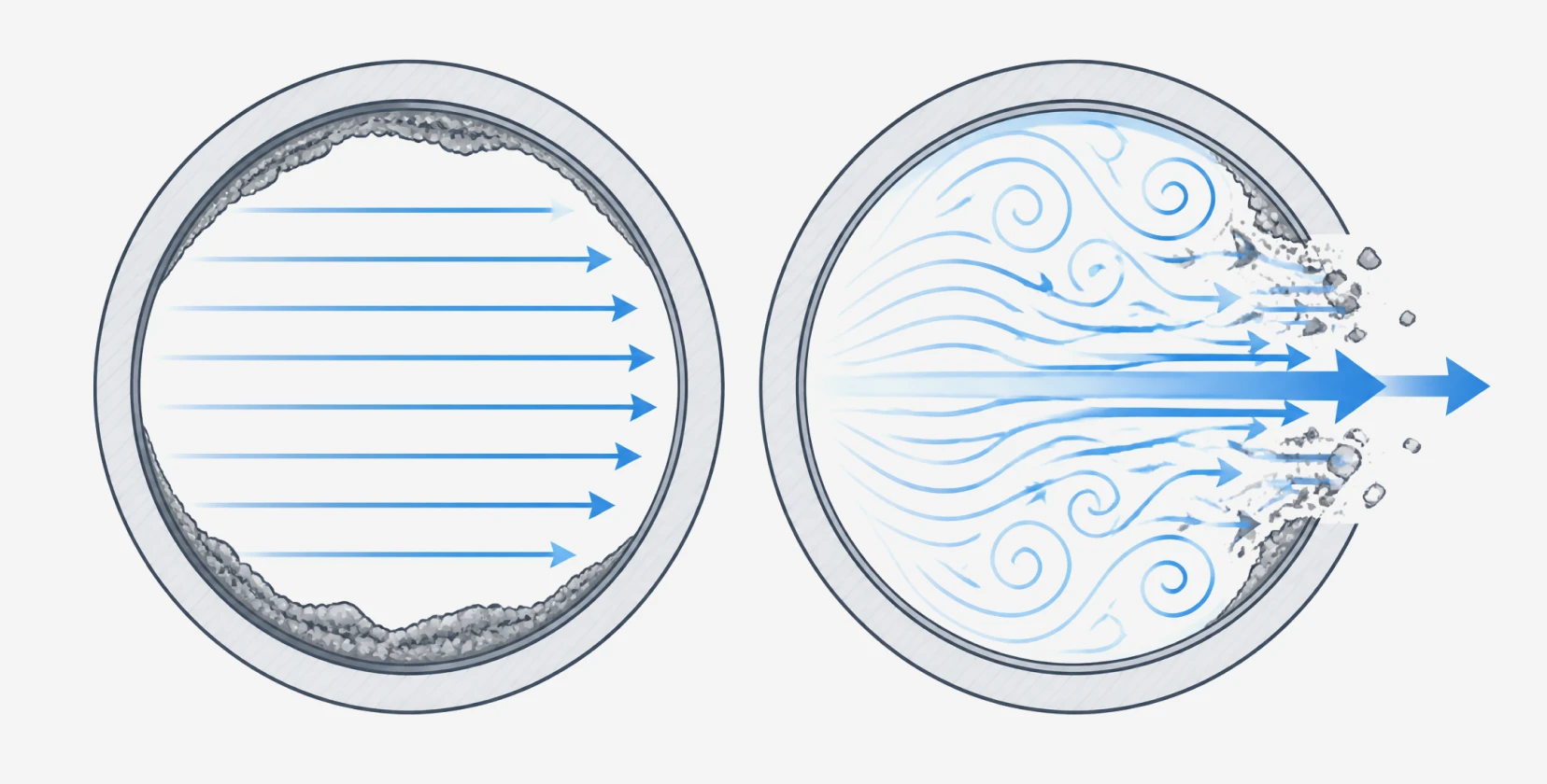
CIP cleaning rests on four interdependent factors: temperature, chemical action, time, and mechanical action. The first three are set by the program; the fourth is delivered entirely by the pump. Mechanical scouring requires turbulent flow, and the validated industry minimum is a linear velocity of 1.5 m/s in the piping, which places the Reynolds number well above 10,000 for typical cleaning solutions. Below this threshold, flow turns laminar, the solution slides past the pipe wall without shear force, and protein and mineral films remain in place regardless of chemical concentration or temperature.
The velocity requirement also applies to air removal: studies on cleaning hydraulics show that roughly 1.5 m/s is the minimum velocity that sweeps trapped air out of bends, dead legs, and high points, and air pockets block solution contact as effectively as a closed valve. For tank cleaning through spray devices, the pressure requirement sits on top of the velocity requirement: static spray balls need 1.5 to 3 bar at the device inlet, and rotating jet cleaners need 3 to 7 bar or more. The pump curve must clear the highest of these demands, not the average.
What the Cleaning Cycle Does to the Pump
A standard five-phase CIP program subjects the pump to a sequence of chemically and thermally distinct fluids within a single cycle:
| Phase | Medium | Temperature | Stress on the pump |
|---|---|---|---|
| Pre-rinse | Recovered or potable water | Ambient to 40 °C | High flow, entrained air on return, possible product solids |
| Caustic wash | 1–2% sodium hydroxide | 70–85 °C | Chemical attack on elastomers, thermal stress on seals |
| Intermediate rinse | Potable water | Ambient | Thermal shock swing from 80 °C to ambient within minutes |
| Acid wash | 0.5–1.5% nitric or phosphoric acid | 50–75 °C | Acid corrosion of susceptible alloys and brazed joints |
| Final rinse / sanitize | Purified water, peracetic acid | Ambient to 60 °C | Oxidizing sanitizer attack on elastomer seals |
Two facts stand out from this table. First, the pump sees several full thermal swings per cycle, dozens of cycles per week, and the differential expansion between seal faces, seat holders, and casings is what opens leakage paths. Second, the elastomer that survives hot caustic is not automatically the elastomer that survives hot acid and peracetic acid, which is why seal and gasket material selection belongs in the pump specification, not in a maintenance replacement schedule.
Sizing the CIP Supply Pump
Supply pump sizing starts from velocity, not from tank volume. The required flow is the pipe cross-sectional area multiplied by 1.5 m/s minimum, calculated for every line diameter in the circuit. As a reference, a DN80 (3-inch) line requires roughly 24 m³/h and a DN100 (4-inch) header roughly 42 m³/h to hold the threshold.
Where the circuit includes branches of different diameters and lengths, the sizing case is the hydraulically worst branch—the one with the highest friction loss at the required velocity—because flow distributes toward the path of least resistance and starves the high-resistance legs. This is the most common field failure in CIP hydraulics: instruments at the pump discharge show healthy flow while a starved branch runs at half the required velocity, and the cycle record shows a completed clean that never happened in that leg. On top of the velocity flow, the pump head must cover pipe friction at that flow, elevation change, spray device inlet pressure, and control valve drop. A practical margin of 10 to 20 percent on flow accommodates impeller wear over the maintenance interval.
Engineering the CIP Return Pump
The return pump carries the harder job. Its task is to keep the cleaned vessel or line empty while solution arrives continuously, which means it must pump a mixture of liquid and entrained air, self-prime from an empty line at the start of each phase, and do so at a flow deliberately larger than the supply flow. Design practice sizes return capacity at 10 to 30 percent above supply capacity so the vessel bottom never accumulates solution; a flooded bottom dilutes chemistry, breaks the falling-film cleaning action on vessel walls, and can push cleaning fluid into product zones.
Standard centrifugal pumps cannot perform this duty because they lose prime on air ingress. The two established architectures are self-priming liquid-ring pumps, which tolerate air-liquid mixtures continuously, and centrifugal pumps with air-screw or vacuum-assist priming stages. Return pump NPSH also deserves a hard check: the pump draws from an open vessel at up to 85 °C, where water vapor pressure has consumed a large share of atmospheric head. A return pump that cavitates mid-cycle breaks circuit balance exactly when the supply pump is still delivering. For strategies to combat this, refer to our insights on industrial cavitation prevention.
Materials and Seals for Caustic, Acid, and Thermal Shock
Wetted construction for CIP duty converges on a short list. Casing and impeller in AISI 316L stainless steel cover the full phase sequence, including hot nitric acid, provided the steel is properly passivated and welds are pickled. Elastomers divide by chemistry: EPDM handles hot caustic and steam well but degrades in oxidizing sanitizers and oils; FKM covers acids and peracetic solutions but performs poorly in hot concentrated caustic; FFKM covers everything at a higher premium. Seal faces should run silicon carbide against silicon carbide, because standard carbon faces blister and wear rapidly under thermal shock.
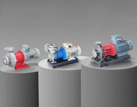
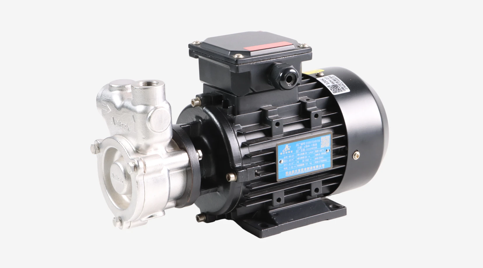
Where the CIP skid serves a chemical plant environment rather than a strict hygienic line, seal-less magnetic drive centrifugal pumps remove the seal from the failure matrix entirely. This eliminates caustic leakage from the maintenance log. Aulank magnetic drive centrifugal pumps in stainless steel cover this industrial CIP class, reflecting the configurations found in our leak-proof pump solutions. For strict hygienic food and pharma skids, the sanitary models detailed in our food pump solutions and the CPS-L high-flow stainless steel centrifugal pump provide robust supply duty within the centrifugal pump range.
Control Details That Protect the Pump and the Process
- Ramp control against water hammer: CIP circuits run faster than production lines, so abrupt pump stops and fast valve closures generate repeated pressure shocks that fatigue seals, gaskets, and instruments. Give the CIP sequence its own acceleration and deceleration VFD ramps, and sequence pump stop before valve closure.
- Flow verification per phase: A flow meter on the supply line, trended per phase against the validated velocity for each line size, catches impeller wear, strainer fouling, and valve drift before a failed cleaning is discovered by a microbiological result.
- Conductivity interlocks: Temperature-compensated conductivity controls chemical dosing and detects rinse endpoints. Interlocking the pump sequence to conductivity confirmation prevents the pump from circulating a wrongly dosed or wrongly routed fluid.
- Dry-run and cavitation protection: Return pumps run dry at every phase change by design, so the chosen architecture must tolerate it; supply pumps feeding from low tank levels at high temperature need level interlocks and, on long circuits, a booster to keep suction pressure above vapor pressure.
A Specification Checklist for CIP Pump Procurement
A pump order that survives commissioning and audits should explicitly state these eight items:
- The required velocity and corresponding flow for every line diameter in the circuit, identifying the worst branch.
- The spray device pressure requirement for every vessel on the circuit.
- The specific pump duty point plotted on the manufacturer's curve, with the wear margin stated.
- The return pump capacity, sized explicitly as a percentage above supply capacity, naming the self-priming architecture.
- Wetted materials and elastomers accurately cross-referenced against each chemical phase and sanitizer in use.
- A thermal cycling statement detailing the number of cycles per day and the extreme temperature swings per cycle.
- Rigorous NPSH verification for the return pump at the absolute hottest return temperature.
- The control integration list: VFD ramps, interlocks, and flow verification points.
Aulank Pump manufactures stainless steel centrifugal and magnetic drive pumps for CIP supply and chemical circulation duty, covering hot caustic, acid, and sanitizer service with 316L construction, SiC seal faces, and seal-less options for industrial cleaning systems. Send us your circuit line sizes, spray device requirements, and cleaning program, and our engineering team will return a matched pump pair with the full sizing calculation. Contact us for a CIP pump review of your skid or retrofit project.