




Batch reactors in pharmaceutical and specialty chemical plants live or die by temperature control. Exothermic synthesis, controlled crystallization cooling ramps, and reflux holding all depend on a heat transfer fluid loop that delivers the right flow at the right temperature for the entire batch cycle. Inside that loop, the circulation pump absorbs the worst abuse in the system: repeated thermal cycling across ranges that can span -80 °C to +300 °C, fluids whose viscosity swings by an order of magnitude between cold start and operating temperature, and continuous-duty schedules with no tolerance for leakage. Pump failures in reactor temperature control loops trace back to specification errors made before purchase far more often than to manufacturing defects. This engineering guide defines the failure mechanisms, matches pump architectures to heat transfer fluids, and sets out the specification protocol for a circulation pump that survives the duty.
Why the Circulation Pump Is the Reliability Bottleneck
A reactor temperature control unit (TCU) imposes a combination of stresses that few other pump applications concentrate in one machine:
- Thermal cycling fatigue: Batch processes heat and cool the same loop repeatedly, sometimes several times per day. Every cycle expands and contracts casings, seal faces, and internal clearances. Mechanical seals designed for steady-state duty lose face flatness under cycling and begin to weep thermal fluid long before their rated life.
- Wide fluid property swings: A water-glycol brine at -40 °C is roughly ten times more viscous than at +40 °C. Silicone oils and synthetic heat transfer fluids behave in reverse, thinning dramatically at temperature. A pump sized on room-temperature viscosity will underperform at one end of the cycle and overload at the other.
- Vapor pressure at the hot end: Heat transfer fluids operated near their boiling or flash points raise the NPSH requirement of the installation. Cavitation inside a TCU pump presents as flow instability and temperature oscillation at the reactor, which operators frequently misdiagnose as a control tuning problem.
- Zero-leakage expectations: Thermal oils smoke and ignite on contact with hot surfaces, and degraded glycol brines corrode surrounding equipment. In pharmaceutical plants, any leaked fluid near a batch vessel is also a contamination event. A dripping seal that would be tolerated in a water plant is a reportable incident in a reactor hall.
Matching the Pump to the Heat Transfer Fluid
The fluid defines the temperature window, and the window defines the pump. Three fluid families cover industrial reactor duty:
| Fluid family | Typical range | Engineering notes for the pump |
|---|---|---|
| Water / tempered water | +5 °C to +160 °C (pressurized) | Excellent heat transfer; watch scaling, corrosion inhibitors, and NPSH at the pressurized hot end |
| Water-glycol brines (EG/PG) | −40 °C to +120 °C | High cold viscosity drives motor sizing; glycol degradation products attack elastomers and braze joints |
| Silicone oils / synthetic HTF | −80 °C to +300 °C and above | Single fluid covers full-range TCUs; low lubricity and high temperature demand seal-less designs and bearing material upgrades |
Full-range TCUs built around one synthetic fluid simplify reactor operation because the same loop heats and cools without fluid changeover, but they transfer the entire temperature burden onto the pump. This is the duty class where pump specification decides plant availability.
Pump Architectures for Reactor TCU Loops
Seal-Less Magnetic Drive Vortex Pumps
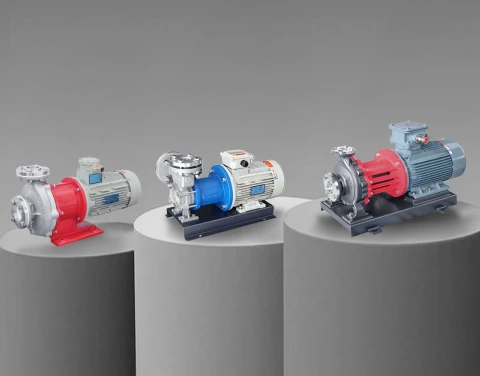
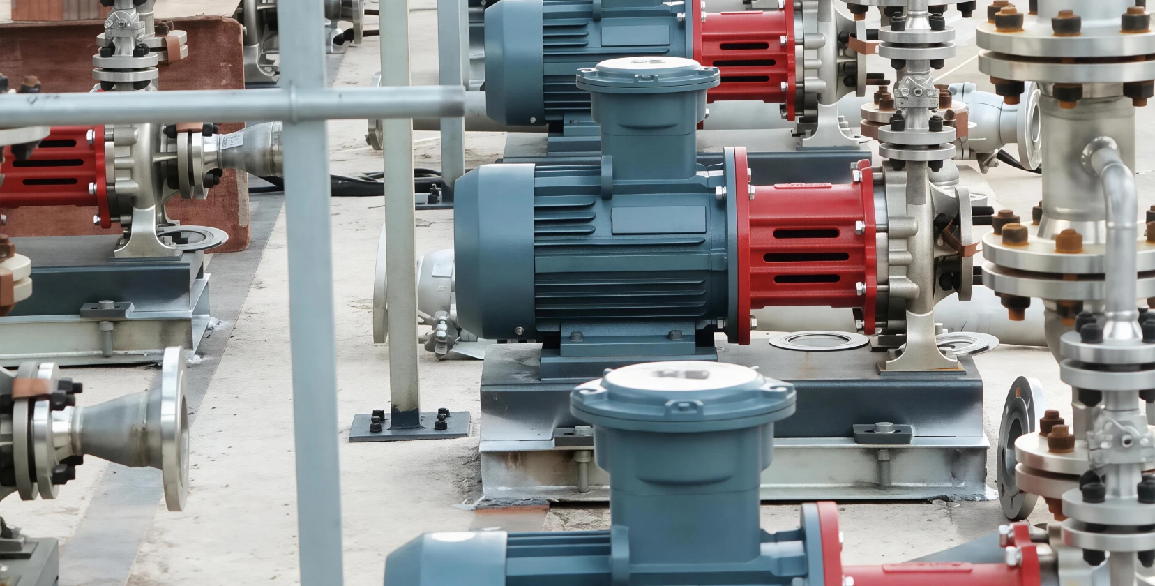
TCU circulation duty is characteristically low-flow and high-head: the loop must overcome jacket nozzle losses, control valve pressure drop, and piping friction while moving only a few cubic meters per hour. Vortex hydraulics generate high head at low specific speed exactly in this regime, and the magnetic drive configuration removes the shaft seal, which is the first component to fail under thermal cycling. With the fluid contained behind a static containment shell, thermal oil leakage, glycol weepage, and seal replacement intervals disappear from the maintenance plan. Aulank MDH stainless steel vortex magnetic drive pumps are built for this duty class, with metallic containment for high-temperature heat transfer fluids and rated windows covering the extremes described in our high-temperature pump solutions. For a broader view of the hydraulic type, see our vortex pump range.
Mechanical Seal Pumps: Where They Still Fit
In tempered water loops below 120 °C with stable chemistry, a well-specified mechanical seal pump remains a valid and economical choice. The seal faces should be silicon carbide against silicon carbide to tolerate thermal shock, and the elastomers must match the inhibitor package. Above this window, or wherever the fluid is a synthetic oil, the lifecycle cost of seal replacements and cleanup routinely exceeds the price delta of a seal-less pump within the first years of operation.
What to Avoid
Standard centrifugal pumps with packing glands have no place in a hot oil or brine TCU loop. Packing requires controlled leakage to survive, and controlled leakage of thermal fluid is precisely the failure mode the plant is trying to eliminate. Plastic-bodied pumps are similarly disqualified from full-range duty by their temperature ceiling, regardless of chemical resistance.
Engineering the Loop Around the Pump
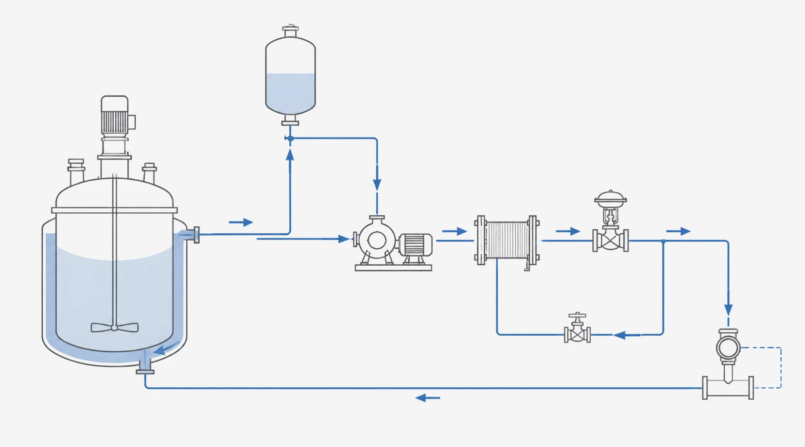
A correctly selected pump still fails in a badly engineered loop. Four loop-level decisions protect the pump across the full temperature cycle:
- Expansion tank sizing and placement: It must be sized for total fluid expansion between the coldest and hottest states, mounted at the suction side high point, and kept below its own temperature limit. An undersized or hot expansion tank pulls the suction pressure down exactly when vapor pressure rises.
- Hot-end NPSH verification: Suction conditions must be verified at the hottest operating point, not at commissioning temperature, because available NPSH falls as fluid vapor pressure climbs.
- Cold-start motor torque: Motor power must cover the cold-start viscosity peak. A motor sized at operating temperature will trip on overload during winter startup on brine loops.
- Protection interlocks: A flow switch or differential pressure monitor interlocked to the heater protects the pump against dry running after a fluid loss, and a small bypass maintains minimum flow when the control valve closes down at setpoint.
Failure Modes the Specification Must Pre-Empt
Field experience with TCU loops converges on four recurring failure modes, each preventable at specification stage:
- Cavitation at the hot end: Pre-empted by the worst-case NPSH check and by selecting a pump whose required NPSH stays low at the duty flow.
- Seal and gasket leakage under cycling: Pre-empted by eliminating the dynamic seal where the fluid justifies it.
- Magnetic coupling decoupling: Occurs when cold viscosity spikes demand more torque than the coupling rating; the fix is torque margin in the coupling selection and, on brine loops, a soft-start or speed ramp that limits startup torque.
- Bearing wear from low-lubricity synthetic oils: Pre-empted by silicon carbide sleeve bearings and an internal flush path that keeps filtered fluid moving across the bearing surfaces at all flow rates.
A Specification Protocol for Reactor TCU Pumps
A defensible TCU pump specification follows a fixed order:
- Define the fluid and its full operating temperature window, including startup and upset states.
- Extract viscosity, density, and vapor pressure at the extremes of that window from the fluid manufacturer's data sheet.
- Calculate the loop pressure drop at duty flow, including the jacket, control valve, heat exchanger, and piping.
- Check NPSH available at the hottest state against pump NPSH required with margin.
- Size motor and coupling against the cold-viscosity torque peak.
- Select the architecture: seal-less magnetic drive for synthetic oils, brines with leakage constraints, and any pharmaceutical environment; mechanical seal with SiC faces only inside the tempered-water window.
- Specify the protection set: flow interlock, minimum-flow bypass, expansion tank level monitoring.
Aulank Pump manufactures vortex, centrifugal, and positive displacement pumps for temperature control loops covering -196 °C to +400 °C, with seal-less magnetic drive configurations, stainless steel construction, and motor options matched to cold-start torque demands. Reactor TCU duty is a standard application class for our engineering team, alongside the pharmaceutical duties covered in our pharmaceutical pump selection guide and the related mold temperature controller pump guide. Send us your fluid data sheet, temperature window, and loop pressure drop, and we will return a matched pump configuration with the full protection specification. Contact us to start the review.