




Back-end test is where semiconductor devices prove they can survive the temperatures their datasheets promise. Handlers cycle packaged devices across −60°C to +160°C while electrical tests run. Wafer probers hold chucks within ±0.2°C across a 300 mm surface. Burn-in chambers stress devices at elevated temperature for days. Thermal shock systems swing samples between extremes in seconds. Every one of these capabilities rests on a thermal management loop, and wherever the loop carries liquid, a circulation pump determines whether the equipment holds its temperature specification hour after hour, cycle after cycle. Test equipment builders focus engineering attention on refrigeration stages and control algorithms, yet field failures in thermal test systems trace back to circulation hardware with remarkable consistency: seal leaks at temperature extremes, pumps that lose head as the fluid gets cold and viscous, and loops that trap air after every service event. This guide covers pump engineering for semiconductor test thermal management: the duty profile, the hardware choices that survive it, and the specification data that produces a reliable match.
Where Liquid Loops Sit on the Test Floor
Test handler thermal conditioning
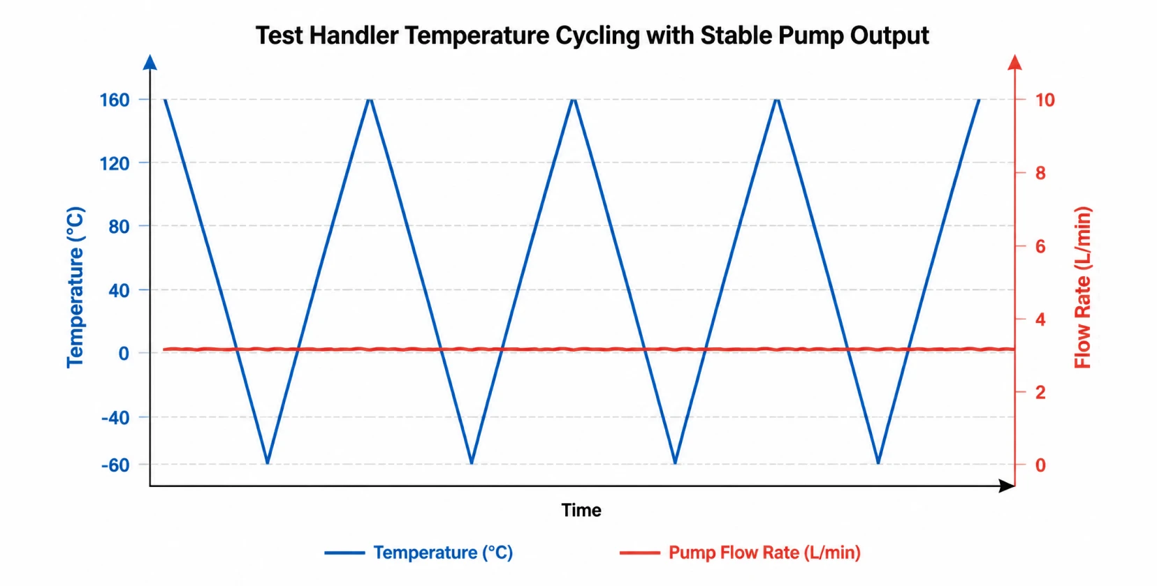
Production handlers bring each device to test temperature before contact, holding soak plates and chucks at setpoints anywhere from −60°C to +160°C depending on the device grade. High-throughput handlers run around the clock, and their thermal conditioning loops ramp continuously between cold and hot test insertion. The circulation pump in these loops sees the full temperature swing as a routine duty cycle, thousands of times per year.
Wafer prober and thermal chuck systems
Analytical and production probers control chuck temperature from −60°C to +150°C and beyond, with spatial uniformity targets as tight as ±0.2°C across the wafer. Liquid-cooled chuck designs circulate conditioned coolant through channels in the chuck body, and temperature uniformity at the wafer surface inherits the flow stability of that circulation loop. Any flow pulsation or air entrainment prints directly onto the measurement.
Burn-in and environmental chamber support
Burn-in chambers hold devices under electrical bias at elevated temperature for early-life failure screening, and liquid-cooled designs circulate heat transfer fluid through chamber walls, load boards, and device sockets to hold uniform conditions under kilowatts of dissipated device power. Environmental and HAST chambers draw on chilled and heated fluid loops for conditioning and condenser cooling. Thermal shock systems based on fluid baths transfer samples between hot and cold liquid directly.
Facility and chiller loops behind the tools
Behind the instruments sit the support loops: chiller secondary circulation, heat exchanger skids, and coolant distribution to rows of test cells. These loops run continuously and determine whether the tools see stable supply conditions at their inlets.
The Duty Profile That Breaks Ordinary Pumps
Test thermal management imposes a combination of stresses that general industrial pump duty rarely combines:
- Extreme temperature swing: the pump casing and wetted parts cycle with the loop, from −60°C cold starts to +200°C or higher conditioning runs, sometimes within the same shift.
- Viscosity extremes: glycol-blended coolants thicken sharply at low temperature, multiplying circuit resistance and shaft power exactly when the loop is asked to perform.
- Continuous thermal cycling: expansion and contraction fatigue seals, gaskets, and joints; dynamic shaft seals are statistically the first component to fail in this duty.
- Zero-leakage expectation: test floors run under the same contamination discipline as the fab, and a weeping seal beside a six-figure test head is a liability, an unplanned downtime event, and a safety issue at high temperature.
- Fast ramps with stable flow: control systems assume constant circulation during ramps; a pump whose output sags at temperature extremes extends soak time on every device tested.
Engineering the Pump for Test Duty
Wide-range media rating with real margin
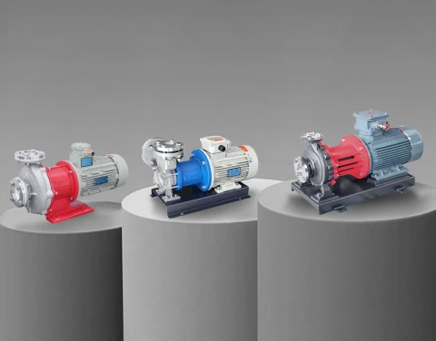
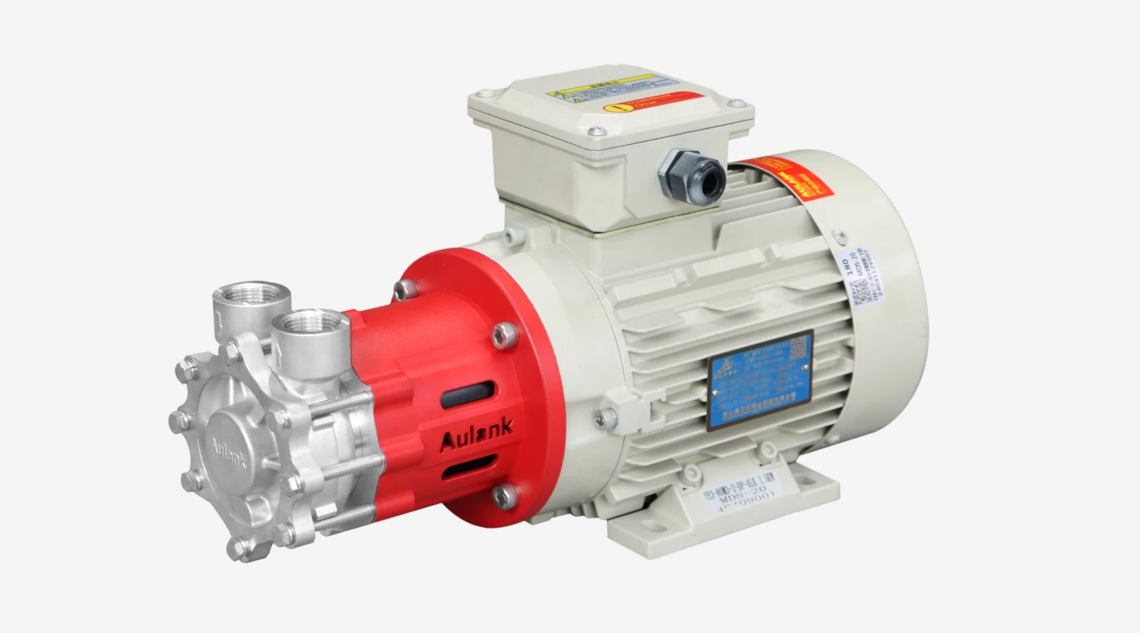
A pump rated narrowly around the duty point has no reserve for the abnormal conditions test loops produce routinely: the cold start at minimum temperature, the conditioning run at maximum, and the transition between them. Vortex magnetic drive pumps rated from −196°C to +400°C place the entire test envelope, including thermal shock and burn-in conditioning duty, inside the rating with margin. The MDH series covers the high-temperature conditioning positions, while the MDS series serves compact tool-integration loops.
Static sealing through the thermal cycles
Magnetic drive construction replaces the dynamic shaft seal with a static isolation sleeve: a single fixed pressure boundary with no wearing faces, no leak path that opens with age, and no elastomer exposed to the temperature extremes. Helium leak-tested assembly documents containment integrity for the quality file. Silicon carbide bearings handle the media temperatures and the low lubricity of cold glycol without the thermal limits that finish conventional seals early.
Stable head across the viscosity range
Cold, viscous coolant raises circuit resistance at the same time the refrigeration stage needs maximum flow. Vortex hydraulics hold high head at low flow on a stable curve, so circulation stays nearly constant from a −40°C cold start to a +150°C conditioning run. That stability is what allows the temperature controller to hold its ramp profile instead of waiting on the hydraulics.
Serviceability: fill, drain, and purge
Test loops get opened for service, fluid changes, and chamber reconfiguration. Trapped air after refill destroys chuck uniformity and extends commissioning. The forward and reverse transfer capability of the MDW series performs fill-and-drain from a single connection, purging air from high points and cutting the time between maintenance and released production.
Fluid Selection Across Test Equipment
| Equipment | Typical fluid | Temperature band | Pump notes |
|---|---|---|---|
| Handlers and chucks | Water-glycol blend | −60°C to +160°C | Viscosity derating at cold end; stable low-flow head |
| Burn-in conditioning | Thermal oil or glycol | Ambient to +200°C | High-temperature magnetic drive; SiC bearings |
| Thermal shock fluid baths | Dielectric fluid | −65°C to +200°C | Confirm fluid compatibility; low lubricity needs hard bearings |
| Chiller secondary loops | Water-glycol blend | −40°C to +90°C | Continuous duty; N+1 redundancy on critical cells |
Throughput Economics: Soak Time Is Money
Test cost per device divides equipment amortization by throughput, and thermal soak time sits directly in the throughput equation. A handler that spends forty seconds bringing each lot to temperature instead of twenty-five loses a measurable percentage of daily capacity, and at production volumes that gap pays for a great deal of thermal hardware. The pump's contribution is flow stability through the ramp: a circulation loop that holds its flow at temperature extremes lets the conditioning stage work at its rated capacity, while a sagging loop stretches every soak. Multi-site test configurations raise the stakes further, because all sites wait on the slowest thermal path in the handler. Engineers evaluating thermal upgrades on existing test cells often find the circulation hardware, sized years earlier for a lighter device load, is the constraint that limits the entire cell.
The same arithmetic runs in reverse for reliability screening. Burn-in capacity is booked in chamber-hours, and chambers sidelined by circulation failures consume the schedule of every qualification program downstream. Specifying circulation pumps with documented containment and thermal-cycle endurance is cheap insurance against the most expensive calendar in the test organization.
Specification Protocol for Test Equipment Builders
A circulation pump matched to test thermal duty starts from complete loop data:
- Fluid identity, concentration, and viscosity at both ends of the operating temperature range.
- Required flow at the chuck or chamber connection, and full circuit pressure drop at the coldest condition.
- Ramp rate target and the soak stability the test specification demands.
- Cycles per day and the temperature swing per cycle, which sets the fatigue exposure of every component.
- Containment documentation: helium leak test records and wetted material certificates.
- Envelope, port positions, and control integration inside the handler, prober, or chamber frame.
Aulank Pump manufactures stainless steel vortex magnetic drive pumps for semiconductor test thermal management, covering media from −196°C to +400°C with helium leak-tested static containment and stable low-flow hydraulics across the MDH, MDW, and MDS series. Related circulation engineering for fab process tools is covered in pump solutions for semiconductor process temperature control, and cleaning-equipment duty in pump solutions for semiconductor wet cleaning systems. Send us your loop schematic and fluid data, and our engineering team will return a matched pump with the sizing calculation. Contact us for a review of your test equipment project.