


A positive displacement pump delivers a fixed volume per revolution or stroke. It does not generate pressure on its own — it overcomes whatever pressure the system puts in front of it. This behavior is fundamentally different from a centrifugal pump, and it changes everything about how you should think about running multiple PD pumps together.
When a single pump cannot meet the flow rate or pressure your system demands, you have two options: put pumps in parallel to get more flow, or put them in series to get more pressure. The concepts sound straightforward, but the engineering details matter. PD pump series and parallel configurations each come with specific design requirements, risk factors, and practical limitations that do not apply to centrifugal pump systems. Getting these details wrong leads to equipment damage, seal failures, or systems that simply do not perform as expected.
This guide walks through both configurations from an engineering standpoint — when each one makes sense, how to design the piping and controls, what can go wrong, and how real systems are actually built in the field.
How Series and Parallel Configurations Work in PD Pump Systems
The basic rules are simple. Parallel means combining flow. Series means combining pressure. But the way PD pumps behave in these configurations is quite different from centrifugal pumps, and the differences are worth understanding before you draw a single P&ID line.
A centrifugal pump has a curved performance characteristic — its flow changes with pressure. When you put two centrifugal pumps in parallel, the combined flow does not simply double, because the system curve shifts and the operating point moves. The actual gain is always less than the theoretical sum. The same applies to centrifugal pumps in series — the combined head is less than the sum of individual heads at the actual operating flow.
PD pumps work differently. Their flow is essentially constant regardless of pressure (within the rated range). So when you put two identical PD pumps in parallel, the system actually gets very close to double the flow. When you put them in series, the system gets very close to double the pressure. The theoretical values hold much more closely in practice. But this same characteristic — the fact that a PD pump will push its rated flow no matter what — is also what makes PD pump configurations more dangerous when something goes wrong.
| Comparison Factor | PD Pumps | Centrifugal Pumps |
|---|---|---|
| Parallel: actual flow gain | Close to theoretical sum | Less than theoretical sum (system curve effect) |
| Series: actual pressure gain | Close to theoretical sum | Less than theoretical sum (system curve effect) |
| Risk if discharge blocked | Pressure rises until something fails | Flow drops to zero, pump churns at shutoff |
| Flow balance in parallel | Sensitive to displacement mismatch | Self-balancing at common header pressure |
| Pulsation interaction | Can amplify if not managed | Minimal concern |
| Relief valve requirement | Mandatory on every pump | Typically not required |
Parallel — Adding Flow
In a parallel configuration, two or more PD pumps draw from a common suction source (or separate sources) and discharge into a common header. Each pump contributes its own flow rate to the total. The system pressure is determined by the downstream resistance and is shared equally across all pumps.
Because PD pumps deliver constant flow at any pressure within their range, the total flow in a parallel system is very nearly the sum of each pump's individual output. If Pump A delivers 10 L/min and Pump B delivers 10 L/min, the system gets approximately 20 L/min. This is a closer match to theory than you would get with centrifugal pumps.
The key requirement is that every pump in a parallel arrangement needs its own check valve on the discharge side. Without it, a stopped pump becomes an open backflow path — the running pump will push fluid backward through the idle pump instead of into the system.
Series — Adding Pressure
In a series configuration, the discharge of the first pump connects to the suction of the second pump. The flow rate through the system is set by a single pump's displacement. The pressures add together — if the first pump generates 5 bar of differential and the second generates another 5 bar, the system sees approximately 10 bar at the final discharge.
Here is the critical point that many engineers underestimate: PD pumps in direct series is not a common arrangement in industrial practice, and for some pump types it is not feasible at all. Reciprocating PD pumps — AODD pumps, piston pumps, diaphragm pumps — produce oscillating, pulsating flow. Connecting two pulsating pumps in direct series without a buffer tank between them creates pressure spikes and flow interruptions that will damage the system. The intake stroke of the second pump pulls against the discharge stroke of the first pump, and the timing mismatch causes cavitation, hammering, and rapid seal failure.
Rotary PD pumps — gear pumps, screw pumps — produce much smoother flow and can be run in direct series under certain conditions. But even with rotary types, the displacement of the first pump must be slightly larger than the second pump. If the second pump tries to pull more fluid than the first pump delivers, it starves and cavitates. If the first pump pushes more than the second accepts, pressure builds between them with nowhere to go. A relief valve between the two pumps is not optional — it is the only thing preventing a rupture.
Parallel System Engineering Design
When to Use Parallel PD Pumps
There are four common situations where parallel configuration is the right answer.
First, your process needs more flow than a single pump can deliver. Maybe the largest available pump in the series you are using tops out at 50 L/min and you need 90 L/min. Two pumps in parallel solve this without moving to a completely different pump platform.
Second, you need redundancy. In any process that runs 24/7 — chemical dosing, thermal management loops, semiconductor fabrication lines — an unplanned pump failure shuts down the entire operation. Running two pumps in a one-duty-one-standby arrangement with automatic switchover keeps the process running while the failed pump is serviced.
Third, your flow demand varies significantly over time. Instead of throttling a single large pump (which wastes energy and, for PD pumps, creates backpressure problems), you can stage multiple smaller pumps. Run one pump at low demand, bring the second online when demand rises. This is more energy-efficient and reduces wear on each individual pump.
Fourth, physical constraints prevent installing a single large pump. Sometimes the available space, the weight limit of a platform, or the voltage available at a location simply cannot support a larger unit. Two smaller pumps side by side may fit where one large pump does not.
Design Requirements for Parallel Operation
Every parallel PD pump system needs these elements to function properly.
Check valves: one on each pump's discharge, between the pump and the common header. This is non-negotiable. A PD pump that stops while the other is running will see full system pressure pushing backward through it. Without a check valve, fluid flows backward through the stopped pump, the system loses pressure, and the running pump may overload trying to compensate.
Matching displacement and speed: PD pumps in parallel should ideally be identical models running at the same speed. If one pump has a larger displacement than the other, it will carry a disproportionate share of the flow. The smaller pump ends up contributing very little while still consuming energy and accumulating run hours. With centrifugal pumps this self-balances at the common header pressure. With PD pumps it does not — each pump pushes its displacement regardless.
Individual relief valves: each pump needs its own pressure relief valve, not a single shared one on the common header. If a downstream blockage occurs and only a shared relief valve exists, the relief path may not handle the combined flow of all pumps simultaneously.
Header sizing: the common discharge header must be sized for the total combined flow. An undersized header creates excessive velocity and friction loss, causing the system pressure to rise beyond what the pumps were selected for.
Start/stop sequencing: when starting a parallel system, bring pumps online one at a time with a short delay between each. Simultaneous starting causes a current spike on the electrical system and a pressure surge on the hydraulic side. When shutting down, the same staggered approach prevents backflow surges through the check valves.
Pulsation in Parallel Systems
If the PD pumps in your parallel system are reciprocating types — piston, plunger, or diaphragm — pulsation management becomes a real concern. Each pump produces its own pulsation pattern, and when these patterns meet in a common header, they can either cancel out or reinforce each other depending on the phase relationship.
When two pumps pulse in sync, the combined pulsation amplitude in the header roughly doubles. This causes pipe vibration, instrument noise, fatigue stress on fittings, and inaccurate flow measurement. When they pulse out of phase, the pulsations partially cancel and the result is smoother.
There are three practical ways to manage this. First, select inherently low-pulsation pump types — gear pumps and screw pumps produce much smoother flow than piston or diaphragm pumps. Second, install pulsation dampeners (bladder-type accumulators or air chambers) on the discharge of each pump before the common header. Third, if you must use reciprocating pumps in parallel, run them at a controlled phase offset — some controllers support this, though it adds system complexity.
Series System Engineering Design
When to Use Series PD Pumps
Series configuration applies in situations where the system pressure demand exceeds what a single pump can deliver. There are four typical scenarios, and they are not all handled the same way.
First, long piping runs with high-viscosity fluids. Viscous media create enormous friction losses in long pipes. A single pump rated for the required flow may not generate enough pressure to push the fluid through the entire run. A second pump in series adds the pressure needed to overcome the additional resistance.
Second, staged pressure building. Some processes require fluid to be brought up to pressure in controlled increments rather than a single jump. Chemical injection into high-pressure pipelines is one example — a booster pump brings the fluid to an intermediate pressure, and a second pump pushes it to the final injection pressure.
Third, poor suction conditions. When the fluid source is below the pump, or when the suction line is long, or when the fluid has a high vapor pressure, the main process pump may not have enough NPSH (Net Positive Suction Head) available to avoid cavitation. A booster pump installed close to the source raises the pressure at the main pump's suction to a safe level.
Fourth — and this is the most common series arrangement in actual industrial practice — using a centrifugal pump as a booster feeding a PD pump. This hybrid approach is covered in detail below because it is far more commonly used than putting two PD pumps directly in series.
Centrifugal Booster Pump Feeding a PD Pump (Most Common Series Arrangement)
In many real systems, the series arrangement is not two PD pumps at all. It is a centrifugal pump providing suction boost to a PD pump that handles the high-pressure work. This is the standard approach in condensate recovery systems, fuel oil transfer stations, and high-pressure chemical injection skids.
The logic is straightforward. Centrifugal pumps are good at moving volume at moderate pressure. PD pumps are good at generating high pressure at a precise flow rate. Combining them plays to each type's strength. The centrifugal pump ensures the PD pump always has adequate inlet pressure, eliminating cavitation risk. The PD pump then takes the pre-pressurized fluid and pushes it to the required discharge pressure.
Start/stop sequence matters here. Always start the centrifugal booster pump first to build up the suction pressure. Once the line between the two pumps is pressurized, start the PD pump. A pressure switch on the interconnecting line can automate this — the PD pump does not start until the booster has established the minimum required pressure. For shutdown, reverse the order: stop the PD pump first, then the centrifugal booster. Running the PD pump without the booster, even briefly, causes suction starvation and cavitation damage.
Select the centrifugal booster with a low suction specific speed for a wider stable operating range. If the PD pump's flow demand varies (for instance, with VFD speed changes), the centrifugal pump needs to accommodate that variation without running off its curve.
Direct PD-to-PD Series: Design Requirements and Risks
Connecting two PD pumps directly in series — one discharging into the other's suction — is possible but carries real engineering risk. It requires more care than any other multi-pump arrangement.
Pressure rating: the second pump's casing, seals, and all connections must be rated for the cumulative pressure. If the first pump generates 10 bar and the second adds another 10 bar, everything on the second pump sees 20 bar. This includes the shaft seal, the housing, and the discharge piping.
Displacement matching: the first pump's displacement should be slightly larger (typically 5–10%) than the second pump's. This small excess capacity ensures the second pump always has adequate supply. The excess fluid is routed back through a relief valve on the first pump's discharge. Without this margin, any small variation in speed or wear condition causes the second pump to starve.
Interstage relief valve: a pressure relief valve must be installed on the line between the two pumps, set to the rated discharge pressure of the first pump. This protects against overpressure if the second pump stalls or if there is any momentary flow mismatch.
Buffer volume for reciprocating types: if either pump in the series pair is a reciprocating type (piston, plunger, diaphragm, AODD), a buffer vessel between them is mandatory. The pulsating output of the first pump does not match the pulsating demand of the second pump. Without a buffer to absorb these mismatches, the system experiences severe pressure spikes and flow interruptions. Rotary PD pumps (gear, screw) can often be connected directly without a buffer, provided the displacement matching and relief valve requirements are met.
The following table summarizes how feasible direct series operation is for each common PD pump type.
| Pump Type | Direct Series Feasibility | Required Protection | Practical Frequency |
|---|---|---|---|
| Gear Pump | Feasible | Interstage relief valve, displacement margin | Occasional — used in lubrication and chemical systems |
| Screw Pump | Feasible | Interstage relief valve, displacement margin | Occasional — used in fuel oil and crude oil systems |
| Lobe Pump | Possible with care | Relief valve, close speed synchronization | Rare |
| Piston/Plunger Pump | Not recommended without buffer tank | Buffer vessel, relief valve, dampeners | Very rare in direct series |
| AODD Pump | Not feasible | — | Never used in direct series |
| Diaphragm Metering Pump | Not recommended without buffer tank | Buffer vessel, back-pressure valve | Very rare |
Quick Decision: Series or Parallel?
Most of the time, the decision is simple. If your system needs more flow than one pump can provide, go parallel. If your system needs more pressure than one pump can provide, check first whether a higher-pressure-rated single pump exists — that is almost always a better solution than series. If a single pump truly cannot reach the required pressure, consider a centrifugal booster feeding your PD pump before committing to a direct PD-to-PD series setup.
If you need both more flow and more pressure, you are looking at a combination: parallel pumps for the flow, with the parallel set sized for a higher pressure rating, or a parallel set feeding into a series booster stage.
If your primary concern is reliability and uptime rather than performance, the answer is parallel with one-duty-one-standby and automatic switchover.
The choice of pump type also affects which configurations are practical. Gear pumps and screw pumps work well in both series and parallel arrangements because of their smooth, low-pulsation output. Reciprocating types are suitable for parallel duty but should generally be avoided in direct series without buffering. A complete overview of each pump type's characteristics is available in our guide to the different types of positive displacement pumps.
| Your Situation | Recommended Configuration | Reason | Watch Out For |
|---|---|---|---|
| Need more flow, pressure is fine | Parallel | Each pump adds flow at existing system pressure | Check valves, displacement matching |
| Need more pressure, flow is fine | Single higher-rated pump (first choice) or centrifugal booster + PD pump | Avoid complexity of direct PD series | Booster pump NPSH, start/stop sequence |
| Need more pressure, no single pump option | Direct PD series (rotary types only) | Last resort when no single pump covers the pressure | Displacement margin, interstage relief, casing ratings |
| Need uptime and redundancy | Parallel, one-duty-one-standby | Automatic failover keeps process running | Switchover valve logic, alarm on standby failure |
| Need more flow AND more pressure | Parallel set + series booster stage | Parallel handles flow, series handles pressure | Most complex — requires careful system modeling |
| Poor suction conditions | Centrifugal booster feeding PD pump | Booster provides NPSH for PD pump | Start centrifugal first, stop PD first |
Real-World Application Examples
High-Viscosity Chemical Transfer Over Long Piping — Series Configuration
A chemical plant needs to transfer resin at 15,000 cP from a reactor vessel to a filling station 200 meters away. At this viscosity and pipe length, the friction loss through the 2-inch pipe exceeds 12 bar. The available gear pump model delivers the required 8 L/min flow but is rated for 10 bar maximum differential pressure. One pump is not enough.
The solution is two magnetic drive gear pumps in series. The first pump, located at the reactor, pushes resin through the first 100 meters of pipe, generating roughly 6 bar of differential. The second pump, installed at the midpoint, adds another 6 bar to push the resin through the remaining distance. The first pump has a 10% larger displacement than the second, with a relief valve set at 7 bar returning excess flow to the reactor. Both pumps use sealless magnetic drive — at 12 bar cumulative pressure, even a minor shaft seal leak would create a safety hazard with reactive resin. The MDC-X series handles this viscosity range and provides the zero-leakage containment the process demands.
Semiconductor Dosing Line Redundancy — Parallel Configuration
A semiconductor fab runs a chemical mechanical polishing (CMP) slurry dosing system that operates continuously. The dosing pump delivers 200 mL/min of alkaline slurry at ±1% accuracy. A pump failure means the entire CMP station goes down, and restarting a CMP process after an interruption wastes hours of production time and thousands of dollars in ruined wafers.
The system uses two micro magnetic gear pumps in parallel — one active, one on hot standby. Both pumps run continuously at the same speed, but the standby pump discharges through a normally-closed valve. When the active pump's flow sensor detects a deviation beyond ±2%, the controller opens the standby valve and closes the active pump's valve in under 500 milliseconds. The switchover is seamless to the process. Because gear pumps produce near-zero pulsation, the transition does not create a flow disturbance. The MDC-M series is sized for this application with its precision metering accuracy and compact footprint.
Battery Thermal Test System — Centrifugal Booster Plus Gear Pump
An EV battery test equipment manufacturer builds thermal cycling chambers that simulate real driving conditions. The cooling loop circulates ethylene glycol through battery modules at temperatures from -40°C to +120°C. The system needs 15 L/min at 8 bar discharge pressure, with the gear pump handling precise temperature-controlled flow.
At -40°C, the glycol viscosity rises above 200 cP, and the long piping run from the chiller to the test chamber creates significant suction-side friction loss. The gear pump's NPSH requirement cannot be met from the chiller's gravity head alone at cold temperatures.
A small centrifugal booster pump is installed between the chiller outlet and the gear pump inlet. The booster adds 2 bar of suction pressure, ensuring the gear pump always sees positive inlet conditions even at the coldest operating point. The centrifugal pump starts first, builds line pressure, and the gear pump starts on a pressure switch confirmation. On shutdown, the gear pump stops first, the booster runs for five more seconds to flush the line, then shuts down. The MDC-K series gear pump handles the temperature range with its dual seal option (magnetic drive or mechanical seal) and ceramic bearing system that tolerates the wide viscosity swing from cold start to hot operation.
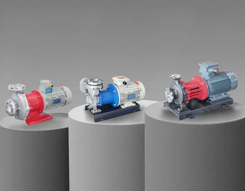
Aulank PD Pumps for Series and Parallel Systems
Aulank's magnetic drive gear pump series is particularly well suited for multi-pump configurations. The sealless magnetic coupling eliminates the shaft seal — which is the component most likely to fail when a pump operates at elevated pressures in a series system. In a direct series arrangement where the second pump sees cumulative pressure, a conventional mechanical seal is pushed beyond its design limit. A magnetic drive pump removes that failure mode entirely.
For parallel systems, the low-pulsation characteristic of gear pump output means that combining flows from two pumps into a common header creates minimal flow disturbance. No pulsation dampeners are needed, and standard check valves handle the backflow protection without hammering or chattering.
The wide viscosity range across Aulank's gear pump models — from below 1 cP to over 38,000 cP — also addresses a practical challenge in series systems: viscosity often changes along the pumping path due to temperature variation. A pump that maintains stable performance across a broad viscosity window prevents the kind of flow mismatch between series stages that leads to cavitation or overpressure.
| Model | Pump Type | Best Configuration | Temperature Range | Key Advantage for Multi-Pump Use |
|---|---|---|---|---|
| MDC-X | Medium/Large Magnetic Gear Pump | Series (high-viscosity long runs) or Parallel (high-flow chemical transfer) | -40°C to +400°C | Handles up to 38,000 cps; zero leakage under cumulative series pressure |
| MDC-M | Micro/Mini Magnetic Gear Pump | Parallel (one-duty-one-standby precision dosing) | -135°C to +180°C | Pulsation-free output for seamless parallel switchover; ±1% metering accuracy |
| MDC-K | Magnetic / Mechanical Seal Gear Pump | Series with centrifugal booster (thermal management) or Parallel (variable-demand systems) | -60°C to +230°C | Dual seal option for flexible system integration; low noise ≤19 dB |
For system-level configuration support — including pump sizing for series/parallel arrangements, interstage protection design, and control logic recommendations — contact the Aulank engineering team with your process parameters.
Frequently Asked Questions
What is the difference between positive displacement pumps in series and in parallel?
Parallel means multiple pumps discharge into the same line — the system gets more flow while pressure stays the same. Series means one pump feeds into the next — the system gets more pressure while flow stays the same. For PD pumps specifically, the combined flow in parallel and combined pressure in series both come very close to the theoretical sum of the individual pumps, because PD pumps deliver constant flow regardless of pressure. This is different from centrifugal pumps, where the actual gain is always less than the sum due to system curve interaction.
Can you run two positive displacement pumps in parallel?
Yes. Parallel operation is the most common multi-pump configuration for PD pumps and works well when designed correctly. Each pump needs its own discharge check valve to prevent backflow through a stopped pump. The pumps should be the same model and speed to ensure balanced flow sharing. For reciprocating PD pumps with high pulsation (piston, diaphragm), consider pulsation dampeners on each pump's discharge before the common header to prevent pulsation interference.
Do positive displacement pumps need check valves in parallel systems?
Yes, every PD pump in a parallel system must have a check valve on its discharge. Without check valves, when one pump stops, the running pump pushes fluid backward through the stopped pump instead of into the system. This causes loss of system pressure, wasted energy, and potential reverse rotation damage to the stopped pump. The check valve must be rated for the full system pressure and installed between the pump discharge and the point where the lines merge into the common header.
What happens if a positive displacement pump is deadheaded in a series system?
If the discharge of the downstream pump is blocked (deadheaded) in a series arrangement, pressure builds continuously because PD pumps keep pushing fluid regardless of downstream conditions. The pressure will rise until something fails — typically a pipe joint, a seal, or the pump casing itself. This is why every PD pump installation, and especially series configurations, requires a pressure relief valve. In a series system, both an interstage relief valve (between the two pumps) and a final discharge relief valve (after the last pump) are mandatory safety devices.
Is it better to use series or parallel for high-viscosity pumping?
It depends on what the system is short of. If a single pump provides enough pressure but not enough flow for your high-viscosity application, use parallel. If the pump provides enough flow but the viscous fluid creates so much friction in the piping that one pump cannot generate the required pressure, use series. In practice, high-viscosity applications more often need series configuration because viscous fluids create very high friction losses in long pipe runs — the pressure demand increases while the flow demand usually stays moderate.
Can a positive displacement pump run backwards?
Many rotary PD pumps — gear pumps, lobe pumps, and screw pumps — can physically run in reverse and will pump fluid in the opposite direction. This is sometimes used intentionally for line clearing or reversing flow direction. However, reciprocating PD pumps (piston, plunger, diaphragm) cannot usefully run backward because their check valves only allow flow in one direction. In parallel systems, backward rotation is a concern when one pump stops while the other keeps running — system pressure can spin the stopped pump backward if no check valve is installed, potentially causing mechanical damage.
Can a positive displacement pump be used in series with a centrifugal pump?
Yes, and this is actually the most common series pump arrangement in industrial systems. A centrifugal pump is installed upstream as a booster to provide adequate suction pressure (NPSH) to the PD pump, which then generates the high discharge pressure the process needs. This combination plays to each pump type's strength — the centrifugal pump moves volume efficiently at moderate pressure, and the PD pump converts that into precise, high-pressure flow. Start the centrifugal pump first to build suction pressure, then start the PD pump. For shutdown, stop the PD pump first, then the centrifugal.
