


The circulation pump is what keeps a thermal oil heating system alive. It pushes hot oil through the loop — from the heat source to the process equipment and back again. If the pump stops, the oil stops moving, heat delivery stops, and your process temperature drops.
This article explains how a thermal oil circulation pump works within a heating system, where it should be installed, how to determine the right flow rate and head for your system, what happens during a cold start, and what sizing mistakes we see most often in the field. If you are designing a new thermal oil system or replacing a circulation pump in an existing one, this guide gives you the practical foundation to get it right.
For our full range of hot oil pump models and specifications, visit the hot oil pump product page.
What Does a Circulation Pump Do in a Thermal Oil Heating System?
A thermal oil circulation pump provides the flow and pressure needed to move heat transfer oil through a closed-loop heating system. The pump itself does not heat the oil. Its job is to keep the oil moving at a steady rate so that heat is carried from the source to wherever it is needed — and then brought back for reheating.
In practical terms, the circulation pump determines whether your system delivers the right amount of heat to each piece of process equipment. If the pump flow is too low, the equipment does not reach target temperature. If head is insufficient, oil cannot overcome the resistance in the piping, and flow drops. The pump sets the pace for the entire thermal loop.
This is why pump selection for a thermal oil system is not just about picking a model from a catalog. It requires understanding the system layout, the total heat load, the piping resistance, and the oil properties at different temperatures.
How a Thermal Oil Circulation System Works
The Circulation Loop — Step by Step
A thermal oil heating system is a closed loop. The oil circulates continuously through the same path:
The heat source — a thermal oil boiler, electric heater, or fired heater — raises the oil temperature to the setpoint. The circulation pump then pushes the heated oil into the supply header. From there, the oil branches out to individual process loads: mold temperature controllers, reactor jackets, heat exchangers, drying rollers, or hot presses. At each load, the oil transfers heat to the process and its temperature drops. The cooled oil collects in the return header and flows back through the return piping. Before reaching the pump inlet, the oil typically passes through an expansion tank (which compensates for thermal expansion and removes dissolved gas) and a filter (which catches particles before they enter the pump). The pump draws in this return oil and sends it back to the heater. The cycle repeats continuously.
In most systems, the oil temperature at the supply side might be 280–320°C, while the return side runs 20–50°C lower. The pump operates on the return side, where the oil is cooler.

Key System Components Around the Pump
Several components directly affect how the circulation pump operates:
Expansion tank — Sits at the highest point of the system. It absorbs the volume increase when oil heats up and expands, and allows dissolved air or gas to separate from the oil. This protects the pump from vapor ingestion.
Filter / strainer — Installed on the suction side or return line before the pump. It catches carbon residue, metal particles, and debris that would otherwise damage the impeller, bearings, or mechanical seal.
Safety valve — Protects the system from overpressure. Usually installed on the supply side near the heater.
Temperature and pressure sensors — Installed at the pump inlet and outlet, and at the heater, to monitor system conditions and trigger alarms if values go out of range.
Where to Install the Circulation Pump
In most thermal oil systems, the circulation pump is installed on the return line — after the expansion tank and filter, and before the heater inlet. This is the low-temperature side of the loop.
There are good reasons for this placement. The oil returning from the process equipment is cooler than the supply oil, typically by 20–50°C. Lower oil temperature means lower thermal stress on the pump's seals, bearings, and gaskets. It also means the oil is denser and has a higher vapor pressure margin, which reduces the risk of cavitation at the pump suction.
The expansion tank, positioned above the pump, provides a positive static head at the pump inlet. This helps ensure that the pump always has oil available at its suction — a basic requirement for stable operation and cavitation prevention.
When installing the pump, keep these points in mind:
- The suction pipe should be as short and straight as possible. Long suction runs with many bends increase friction loss and reduce the available NPSH (Net Positive Suction Head) at the pump.
- Avoid high spots in the suction piping that can trap air pockets. Air in the suction line causes intermittent flow loss and cavitation.
- The pump foundation should be rigid and level. Thermal oil pumps run continuously, and any misalignment between pump and motor increases vibration and shortens bearing life.
- Leave enough clearance around the pump for inspection and maintenance access — especially for mechanical seal replacement on centrifugal models like the WRY-H coupled centrifugal hot oil pump.
Cold Start Conditions — What Happens When the Oil Is Cold
This is something many engineers overlook during pump selection, and it causes real problems on site.
Thermal oil viscosity changes dramatically with temperature. At working temperature — say 280°C — a typical heat transfer oil has a very low viscosity, somewhere around 0.5–1.0 cSt. But at ambient temperature — 20°C or 30°C — the same oil might be 20–50 cSt or higher, depending on the grade. Some oils go above 100 cSt when cold.
This means that during a cold start, the pump has to push oil that is tens of times thicker than what it handles during normal operation. The consequences are real:
- Higher suction resistance — Cold, viscous oil does not flow easily into the pump. The available NPSH at the pump inlet drops, increasing the risk of cavitation.
- Higher motor load — The pump needs more torque to move thick oil. If the motor is sized only for hot-oil conditions, it may trip on overload during a cold start.
- Reduced flow — At high viscosity, pump performance falls off. The actual flow and head are both lower than the catalog values (which are based on water or low-viscosity fluids at 20°C).
How to handle this:
- Use a variable frequency drive (VFD) to start the pump at low speed. Circulate the cold oil slowly until the heater raises the oil temperature enough to reduce viscosity. Then ramp up to full speed.
- When sizing the motor, account for the cold-start torque requirement — not just the steady-state operating point.
- Check the oil manufacturer's viscosity-temperature data and verify that NPSH is adequate at the expected cold-start temperature.
If your system goes through frequent start-stop cycles rather than running continuously, cold-start performance becomes even more important in pump selection.
How to Size a Thermal Oil Circulation Pump
Determining the Required Flow Rate
The flow rate of a thermal oil circulation pump is determined by the total heat load of the system and the temperature difference between supply and return oil. The basic formula is:
Q = P / (ρ × Cp × ΔT)
Where:
- Q = volumetric flow rate (m³/h)
- P = total thermal power / heat load (kW)
- ρ = density of thermal oil at operating temperature (kg/m³)
- Cp = specific heat capacity of the oil (kJ/kg·°C)
- ΔT = temperature difference between supply and return (°C)
For example: if your system delivers 200 kW of heat, the oil density at operating temperature is 780 kg/m³, specific heat is 2.5 kJ/kg·°C, and the supply-return temperature difference is 30°C, then:
Q = 200 / (780 × 2.5 × 30 / 3600) ≈ 12.3 m³/h
This gives you the minimum circulation flow rate. In practice, a small margin (10–15%) is added to account for heat losses in the piping and real-world variations.
Determining the Required Head
Head is the pressure the pump needs to generate to push oil through the entire loop. It equals the total resistance of the system, which includes:
- Straight pipe friction loss — Depends on pipe diameter, length, oil viscosity, and flow velocity. Longer runs and smaller pipes mean more friction.
- Fittings and valves — Every elbow, tee, valve, and reducer adds local resistance. These are often expressed as equivalent pipe lengths.
- Heat exchanger and equipment pressure drop — Each piece of process equipment has its own internal resistance. This data comes from the equipment manufacturer.
- Elevation difference — If the oil needs to reach equipment at a higher level, the static head must be included.
Add all these up, and you get the total system head requirement. One important note: because thermal oil viscosity is different from water, the friction factors are different too. Use the viscosity value at your operating temperature for the calculation, not water-based assumptions.
Checking the Operating Point on the Pump Curve
Every pump has a performance curve showing the relationship between flow rate and head. Your system also has a resistance curve that rises as flow increases. The point where these two curves cross is the actual operating point of the pump.
You want this operating point to fall near the pump's best efficiency point (BEP). If the operating point is far to the left of BEP (low flow, high head), the pump runs inefficiently, generates more heat, and the radial loads on the bearings increase. If it is far to the right (high flow, low head), cavitation risk goes up and the motor may overload.
For specific pump performance curves and parameters, check the product pages on our hot oil pump page.
Common Sizing Mistakes and How to Avoid Them
We see the same mistakes come up again and again when customers size thermal oil circulation pumps. Most of them are easy to avoid if you know what to watch for.
Oversizing with too much safety margin. Adding 30–50% to both flow and head "just to be safe" pushes the pump far from its best efficiency point. The result: higher energy consumption, more noise, more vibration, shorter bearing and seal life, and the need for a throttling valve to bring flow back down — which wastes the energy you just oversized for. A 10–15% margin on flow is reasonable. On head, calculate carefully and add a modest margin based on actual uncertainty, not habit.
Focusing on flow but ignoring head. Some buyers pick a pump based on flow rate alone without verifying that the head matches the system resistance. The pump may physically deliver oil, but if head is short, it cannot push the oil through all the piping and equipment at the required rate. The system starves and temperatures fall short.
Ignoring cold-start viscosity. As discussed above, selecting based only on hot-oil conditions while ignoring the cold-start situation can lead to motor overload or cavitation on startup. Always check the oil's viscosity at your lowest expected start temperature.
Neglecting NPSH. If the available NPSH at the pump suction is lower than the pump's required NPSH, cavitation occurs. This damages the impeller, creates noise, and reduces performance over time. Ensure your system layout — particularly the height of the expansion tank above the pump and the suction pipe design — provides adequate NPSH margin.
No provision for future expansion. If you plan to add more process equipment to the loop later, the pump may not have enough capacity to serve the additional loads. It is worth considering this during initial selection. A VFD can help manage variable loads without wasting energy.
Centrifugal vs Magnetic Drive for Circulation
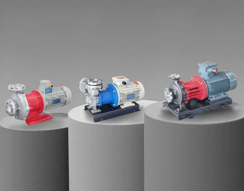
In thermal oil circulation applications, most systems use centrifugal pumps with mechanical seals. The WRY-H series is a good example — a split-body centrifugal pump with air-cooled bearings, handling thermal oil up to 350°C. It covers a wide flow and head range and is easy to maintain. For standard boiler rooms and factory heating systems, this is the practical default choice.
For systems where thermal oil leakage is not tolerable — chemical processing loops, semiconductor TCU circulation, reactor jacket heating in cleanroom-adjacent areas — magnetic drive pumps offer zero-leakage operation by eliminating the mechanical seal entirely. Aulank's MDH magnetic drive vortex pump handles thermal fluids up to 400°C and is used in these safety-critical circulation applications.
The choice comes down to your leakage tolerance, system flow requirements, and maintenance approach. For a deeper comparison including gear pump options, see our upcoming article: Centrifugal vs Gear Hot Oil Pump: Which Type Is Right?
Talk to Us About Your Circulation Pump Requirements
If you are putting together a thermal oil heating system — or troubleshooting an existing one — share your system parameters with us: heat load, operating temperature, piping layout, and any special requirements. We will help you identify the right circulation pump model and configuration.
